
Fire-fighting pipeline transportation device

A technology for transporting devices and fire-fighting pipes, applied in the directions of transport and packaging, single-axle trolleys, trolley accessories, etc., can solve problems such as danger and disengagement, and achieve the effect of avoiding pipe material movement and increasing the effective bearing area.

Inactive Publication Date: 2020-08-04
陶建平
View PDF1 Cites 1 Cited by
  • Summary
  • Abstract
  • Description
  • Claims
  • Application Information

AI Technical Summary

Problems solved by technology

[0004] Based on the technical problem that at least two people are still required to lift the heavy pipeline when loading and unloading the existing transport trolley, which is easy to cause danger due to hands-off, the present invention proposes a fire-fighting pipeline transportation device

Method used


Image

  • Fire-fighting pipeline transportation device
  • Fire-fighting pipeline transportation device
  • Fire-fighting pipeline transportation device

Examples


Embodiment 1

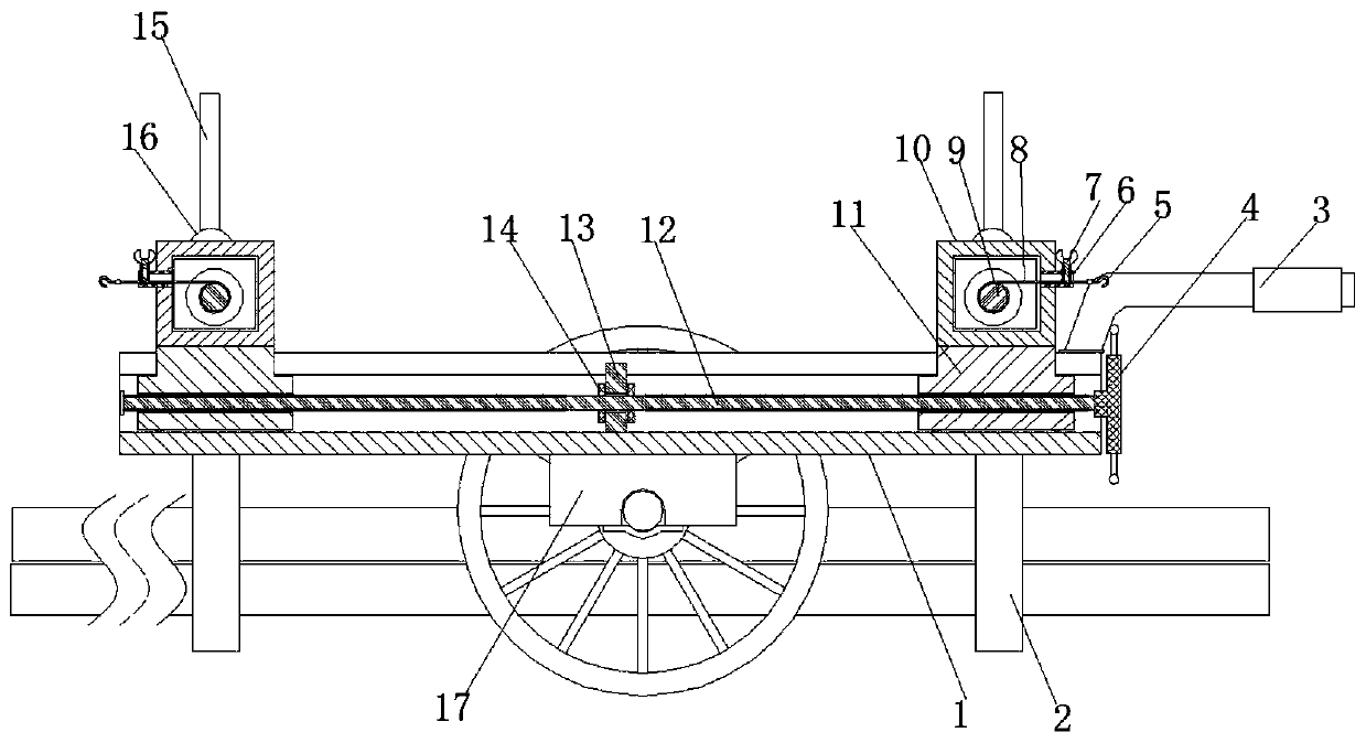
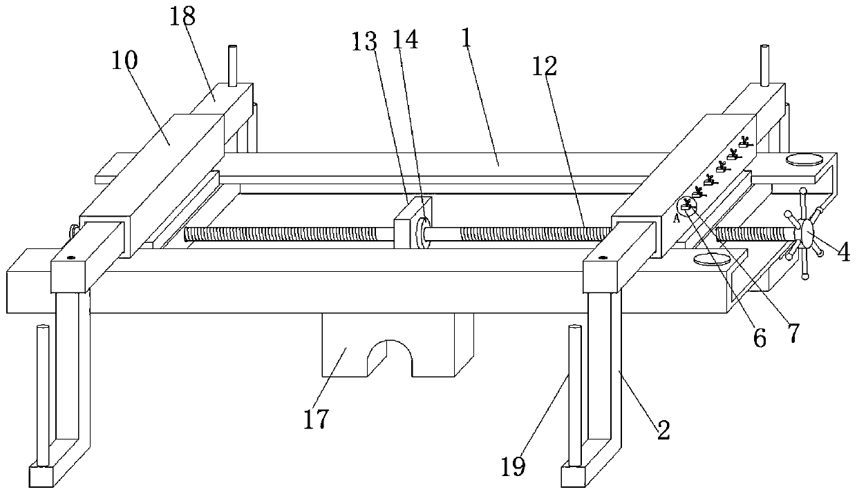
[0029] refer to Figure 1-5 , a fire pipeline transportation device, comprising a trolley base 1 with an upward opening in a C-shaped steel structure, T-shaped sliders 11 are slidably connected to the bottom of the trolley base 1 near both ends, and one of the two T-shaped sliders 11 is opposite to each other. There are coaxially distributed screw holes with opposite thread directions on the side near the middle. The same stud 12 is screwed in the two screw holes. A baffle 13 is fixed in the middle of the bottom of the trolley base 1, and the stud The two ends of the peripheral outer wall of 12 near the baffle plate 13 are all fixed with annular retaining rings 14, and the tops of the two T-shaped sliders 11 are fixed with horizontal tubes 10 by bolts, and the two ends of the horizontal tubes 10 are all inserted with extension rods. 18, and the lower surface of the end of the extension rod 18 is fixed with a support bar 2 of L-shaped structure, and the upper surface end of the...

Embodiment 2

[0038] refer to figure 2 and Figure 5 , a fire-fighting pipeline transportation device. Compared with Embodiment 1, this embodiment also includes that the bottom end of the support rod 2 can also be set as a groove-shaped slide rail 20-shaped structure with the opening upward, and the groove bottom of the groove-shaped slide rail 20 A slide block 24 is slidably connected to the end far away from the support bar 2 , a tension spring 21 is arranged between the outer wall of the slide block 24 and the outer wall of the support bar 2 , and the limit gear bar 19 is fixed on the top of the slide block 24 .

[0039] Wherein, two limiting holes 23 are formed at the end of the groove bottom of the grooved slide rail 20 away from the supporting rod 2 , and the limiting rods 22 are inserted into the two limiting holes 23 .

[0040] When a wider pipe body needs to be placed during use, first pull out the limit rod 22 at the bottom of the groove, and then the pipe body can be clamped be...


PUM


Abstract

The invention belongs to the technical field of fire-fighting pipelines, and particularly relates to a fire-fighting pipeline transportation device, and aims at the problems in the prior art at leasttwo persons are still needed to lift heavy pipelines when the existing transport trolley is loaded and unloaded, and danger is easily caused due to hand disengaging. The following scheme is put forward: the fire-fighting pipeline transportation device comprises a trolley base is of C-shaped steel structure with upward opening. T-shaped sliding blocks are slidably connected to the positions, closeto the two ends, of the bottom of the groove of the trolley base, screw holes which are coaxially distributed and opposite in thread direction are formed in the positions, close to the middle, of theopposite sides of the two T-shaped sliding blocks respectively, and the same double-end stud is screwed into the two screw holes. When the device is in use, only one end of the pipe needs to be placedin the first supporting rod when the pipe body needs to be loaded and unloaded, then the other end of the pipe is clamped in the other supporting rod, and the distance between the two supporting rodscan be adjusted by rotating the shifting wheel before transportation so that the device is suitable for pipes with different lengths.

Description

technical field [0001] The invention relates to the technical field of fire-fighting pipelines, in particular to a fire-fighting pipeline transportation device. Background technique [0002] In the construction of outdoor fire pipes on construction sites, most of the fire pipes used are more than five meters long and made of steel. Due to their heavy weight and easy sliding, and the ground conditions on the construction site are complex. It is very difficult to carry the fire pipes on site, resulting in low construction efficiency, and there are many excavated pipelines on the working face of the construction site, which makes it impossible for large transport vehicles to use. Therefore be badly in need of a kind of simple and easy fire-fighting pipe transportation device, so that the workman can effectively improve the efficient fire-fighting pipe transport vehicle when carrying fire-fighting pipe in the complex environment of construction site. [0003] The retrieved pate...

Claims


Application Information

Patent Timeline
Patent Type & Authority Applications(China)
IPC IPC(8): B62B1/26B62B1/14B62B5/00
CPCB62B1/14B62B1/262B62B1/264B62B5/00B62B2202/02
Inventor 陶建平
Owner 陶建平
Learn More