
Anti-falling collision single-leg buffer structure and leg type undercarriage

A buffer structure and landing gear technology, applied in landing gear, aircraft parts, chassis, etc., can solve problems such as insufficient energy absorption efficiency in crashes

Active Publication Date: 2020-07-31
CHINA AIRPLANT STRENGTH RES INST
View PDF7 Cites 5 Cited by
  • Summary
  • Abstract
  • Description
  • Claims
  • Application Information

AI Technical Summary

Problems solved by technology

Because the traditional landing gear adopts plastic deformation energy absorption or buffer energy absorption, the crash energy absorption efficiency is less than 60%

Method used


Image

  • Anti-falling collision single-leg buffer structure and leg type undercarriage
  • Anti-falling collision single-leg buffer structure and leg type undercarriage
  • Anti-falling collision single-leg buffer structure and leg type undercarriage

Examples


specific Embodiment 1

[0038] Specific embodiment 1: complex ground landing buffer

[0039]When it is applied to the landing buffer on complex ground, it refers to the situation of normal slow landing. At this time, the ground load is small and cannot reach the working start threshold of the tibial buffer 5, so the tibial buffer 5 is in a non-compressed state at this time, which plays a role The role of support during landing. The landing process is in the mode of level 2 buffer.

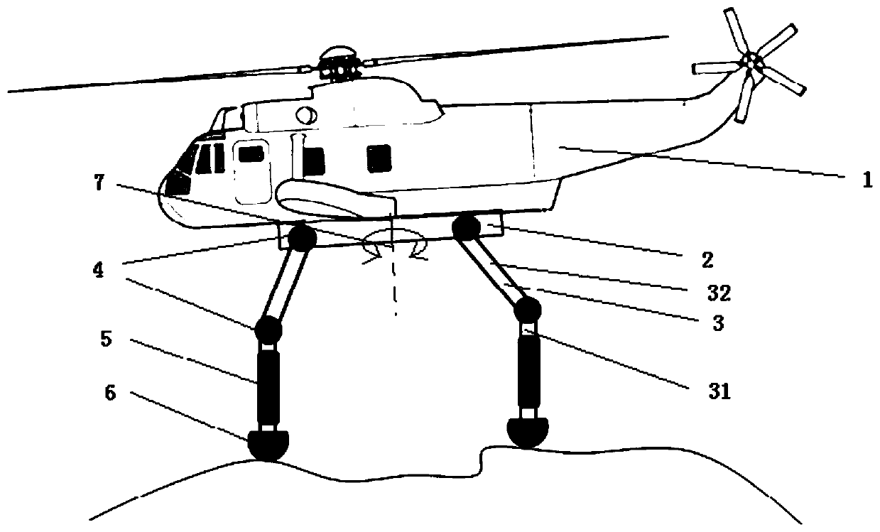
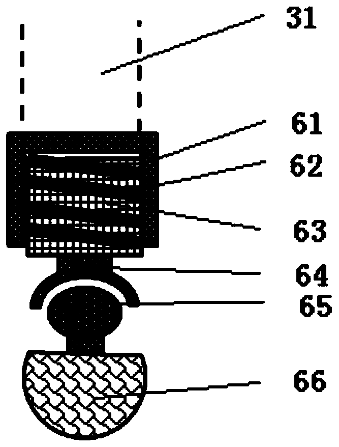
[0040] When landing, first determine the terrain conditions on the ground through the 3D radar system, and the anti-falling leg landing gear 3 completes the pre-swing attitude under the action of the active buffer joint 4 according to the terrain conditions. At this time, the legs should be kept straight and bionic Leg type landing gear tibia 31 is in the state of vertical ground, guarantees that the foot end sole rubber 66 of a plurality of legs touches the ground simultaneously when landing. After the sole rubber 66 t...

specific Embodiment 2

[0044] Specific embodiment 2: emergency crash

[0045] When it is applied to an emergency crash landing, such as falling at a speed of 10.2m / s, the flight control system of the vertical take-off and landing vehicle 1 fails at this time, and timely feedback and real-time control cannot be achieved, and the landing time is relatively short. Due to the large ground load caused by the high landing speed, the tibial bumper 5 reaches the working start threshold, so the tibial bumper 5 is in a passive compression state after landing for the purpose of dissipating energy. Determined based on landing energy. The landing process at this time is the mode of level 3 buffer.

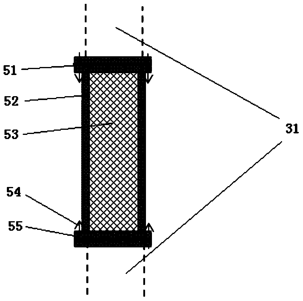
[0046] In addition to the second-level buffering process described in "Specific Example 1: Complex Ground Landing Buffering", the impact state structural failure mode of the filled energy-absorbing material 53 is excited, which can absorb crash energy and reduce vertical impact overload. During the crash process, b...


PUM


Abstract

The invention belongs to the technical field of landing gears of vertical take-off and landing aircrafts, discloses an anti-falling collision single-leg buffer structure and a leg type landing gear, and solves the problems of falling collision and energy absorption in the landing process of a vertical take-off and landing aircraft by adopting an active control method. The undercarriage is designedbased on a bionics concept, a three-stage buffer / impact energy absorption mode of actively controlling to reduce overload peak value, buffer damping energy consumption and structure-controlled shaping deformation damage through mechanism movement is adopted, the impact peak overload is greatly reduced under the assistance of an impedance active control method, and the impact kinetic energy transmitted to the fuselage is effectively reduced, so that the structure safety is improved, and the crash survivability of passengers is improved; and meanwhile, the buffering and energy-absorbing efficiency of the undercarriage is improved, the falling collision and energy absorption requirements of the fuselage are reduced to a certain extent, and positive significance is achieved for reducing the structural weight of the fuselage.

Description

technical field [0001] The invention belongs to the technical field of vertical take-off and landing aircraft landing gear, and in particular relates to an anti-collision single-leg buffer structure and a leg-type landing gear, which are applied to the landing gear design of vertical take-off and landing aircraft for special mission requirements to meet complex and extreme requirements. Anti-collision requirements under the conditions. Background technique [0002] Due to the characteristics of vertical take-off and landing, fixed-point hovering in the air, low-speed flight, low-altitude and ultra-low-altitude flight, in-situ steering, and flight in any direction, the vertical take-off and landing aircraft is limited in take-off and landing sites, and the flying space is small, requiring low-altitude and low-speed tasks. As an ideal aircraft, it has broad application prospects. [0003] At the present stage, most landing gears used in vertical take-off and landing aircraft ...

Claims


Application Information

Patent Timeline
IPC IPC(8): B64C25/62B64C25/26
CPCB64C25/62B64C25/26Y02T50/40
Inventor 任佳王计真刘小川牟让科王彬文
Owner CHINA AIRPLANT STRENGTH RES INST
Learn More