
Honeycomb structure

A honeycomb structure and honeycomb structure technology, applied in the direction of catalyst carrier, ceramic products, separation methods, etc., can solve the problems of emission deterioration and achieve the effect of smaller heat capacity and improved temperature rise

Pending Publication Date: 2020-07-31
NGK INSULATORS LTD
View PDF10 Cites 0 Cited by
  • Summary
  • Abstract
  • Description
  • Claims
  • Application Information

AI Technical Summary

Problems solved by technology

Therefore, there is a problem that the airflow locally concentrates in one compartment, especially under a high load in the driving mode of the car, leading to deterioration of emissions.

Method used


Image

  • Honeycomb structure
  • Honeycomb structure
  • Honeycomb structure

Examples


Embodiment 1

[0091]In Example 1, first, a molding material for producing a honeycomb structure was prepared. Specifically, a binder, a surfactant, a pore-forming material, and water are added to a ceramic raw material to form a molding raw material. It should be noted that kaolin, talc, and alumina, which are cordierite-forming raw materials, were used as ceramic raw materials.

[0092] Next, the obtained molding raw materials are kneaded with a kneader, and then pulverized with a vacuum pulverizer to form clay. Next, the obtained kneaded clay is extruded using a die to produce a honeycomb molded body. As the die, a die formed with a region complementary to the protrusion (the region that becomes the protrusion due to entry of the molded material) is used. After the honeycomb molded body is fired, the thickness of the partition wall is 0.089mm, and the cell density is 62 cells / cm 2 . The cell shape of the honeycomb formed body is quadrilateral. The formed honeycomb body is cylindrical...

Embodiment 2~15

[0110] A honeycomb structure was produced in the same manner as in Example 1 except that the thickness of the partition walls and the configuration of the protrusions were changed as shown in Tables 1 and 2. Also about the honeycomb structures of Examples 2 to 15, the measurement of the pressure loss, the measurement of the temperature rise property, and their judgments were performed by the same method as that of Example 1. Each result is shown in Table 1 and Table 2.


PUM


Abstract

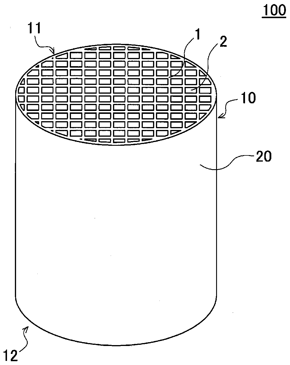
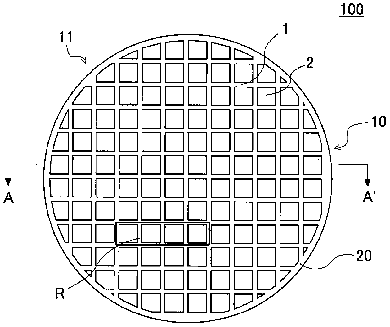
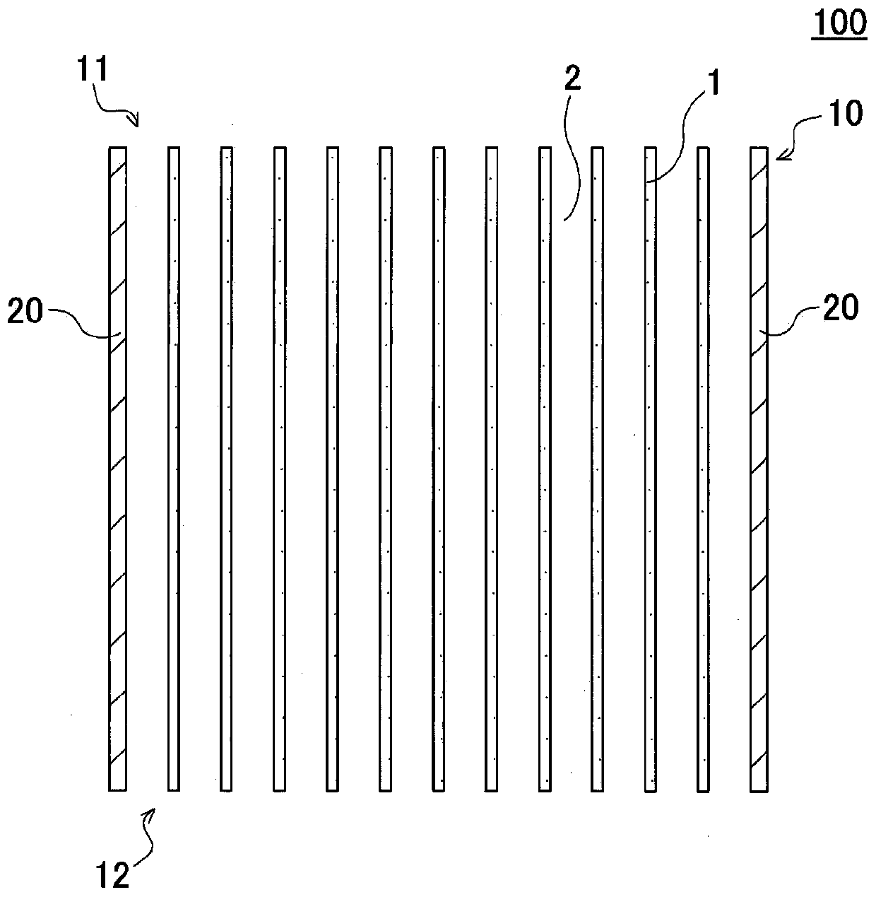
Provided is a honeycomb structure in which an increase in pressure loss can be suppressed and an improvement in temperature increase can be expected. The honeycomb structure includes a pillar-shaped honeycomb structure body having porous partition walls 1 surrounding a plurality of cells 2 which extend from a first to a second end face and which form flow channels of a fluid, and a circumferentialwall enclosing the partition walls, wherein, specific cell of the cells is provided with a pair of projection which projects into the cell from the partition wall, the projection projects, in at least a pair of opposed partition walls among the partition walls 1 constituting the cell, into the cell from a first and a second side, and which is provided continuously in a direction the cell extends,and in the case where the width of a top part 25 of the projection 21 is denoted by W1, and the width of a bottom part 26 of the projection 21 is denoted by W2, W1>W2 holds, and W2 / W1 is 0.5 to 0.9.

Description

technical field [0001] The present invention relates to a honeycomb structure. More specifically, it relates to a honeycomb structure that can be used particularly preferably as a catalyst carrier for supporting a catalyst for purification of exhaust gas. Background technique [0002] In recent years, awareness of environmental issues has increased throughout society. Therefore, in the technical field of generating power by burning fuel, various technologies for removing harmful components such as nitrogen oxides from exhaust gas generated during fuel combustion have been developed. For example, various technologies have been developed for removing harmful components such as nitrogen oxides from exhaust gas emitted from automobile engines. When removing harmful components from exhaust gas like this, a catalyst is usually used to chemically react the harmful components and convert them into other relatively harmless components. In addition, a honeycomb structure is used as...

Claims


Application Information

Patent Timeline
Patent Type & Authority Applications(China)
IPC IPC(8): B01J35/04B01J32/00B01D53/86
CPCB01D53/86B01D46/247B01D46/2474B01D46/2482B01D46/2476B01J35/56C04B38/0009C04B2111/0081B01D46/2498C04B35/185C04B35/195C04B35/478C04B35/565B01D2255/92B01D53/885B01D46/2486
Inventor 高室佑基木下尚志
Owner NGK INSULATORS LTD
Learn More