
An anti-condensation type high heat dissipation outdoor power distribution cabinet

A high heat dissipation, power distribution cabinet technology, applied in substation/distribution device housing, electrical components, substation/switch layout details, etc. The effect of cooling and cooling effect

Active Publication Date: 2021-02-19
胜利油田大源节能设备有限公司
View PDF5 Cites 0 Cited by
  • Summary
  • Abstract
  • Description
  • Claims
  • Application Information

AI Technical Summary

Problems solved by technology

[0005] The purpose of the present invention is to provide an anti-condensation type high heat dissipation outdoor power distribution cabinet with good waterproof and heat dissipation effects for the above problems of poor waterproof and heat dissipation effects

Method used


Image

  • An anti-condensation type high heat dissipation outdoor power distribution cabinet
  • An anti-condensation type high heat dissipation outdoor power distribution cabinet
  • An anti-condensation type high heat dissipation outdoor power distribution cabinet

Examples


Embodiment 1

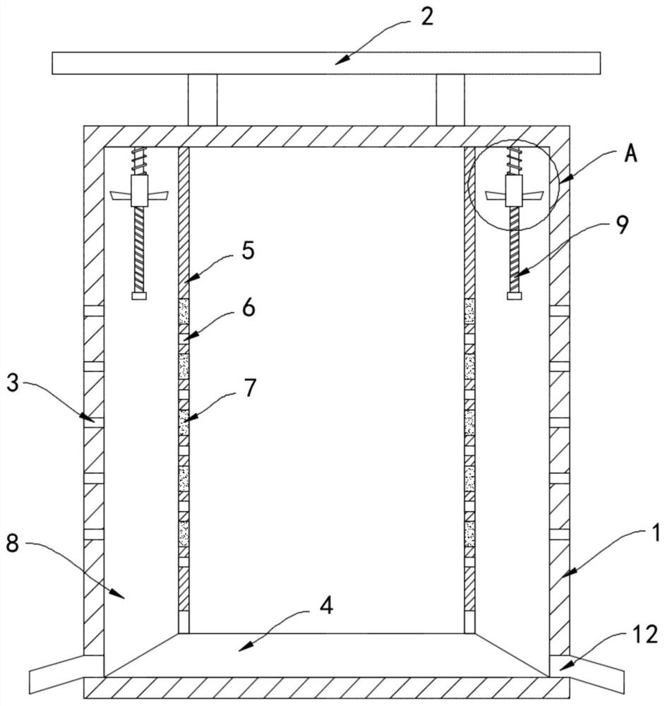
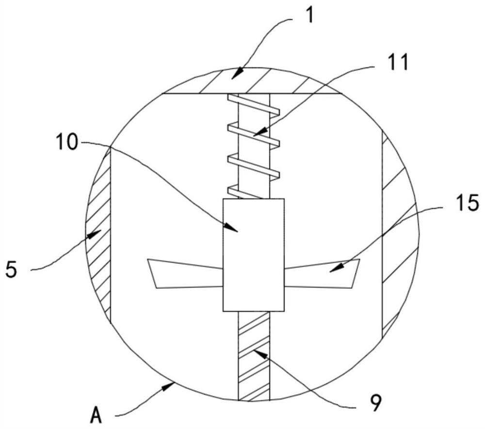
[0022] Such as Figure 1-3 As shown, an anti-condensation type high heat dissipation outdoor power distribution cabinet includes a cabinet body 1, a photovoltaic panel 2 is installed on the upper end of the cabinet body 1, and a plurality of first ventilation openings are provided on the side walls on both sides of the cabinet body 1 3. The inner bottom surface of the cabinet body 1 is equipped with a raised seat 4, and the upper end of the raised seat 4 is installed with a waterproof cover 5 extending in the vertical direction of the cabinet body 1 and arranged in a cylindrical shape. The waterproof cover 5 is arranged in a cylindrical shape, and the waterproof cover 5. It is composed of two semi-arc-shaped cover panels spliced ​​end to end, which is convenient for assembly and disassembly. There are multiple second ventilation openings 6 inside the waterproof cover 5, multiple first ventilation openings 3 and multiple second ventilation openings 6 All are arranged in a stagg...

Embodiment 2

[0029] Such as Figure 4 As shown, the difference between this embodiment and Embodiment 1 is that a ring gear 13 is fixedly sleeved on the side wall of the outer ring of the waterproof cover 5, and the ring gear 13 is arranged in a long cylindrical shape, and the screw nut 10 is installed coaxially on the outside. There is a gear 14 which meshes with the ring gear 13 .

[0030] In this embodiment, when the screw nut 10 rotates, the gear 14 is driven to rotate synchronously, and then the ring gear 13 meshed with it drives the waterproof cover 5 to rotate, and under the action of inertial force, the water condensed on the inner wall of the waterproof cover 5 is promoted. The slipping of the beads is beneficial for the drops of water to drip downwards and be discharged out of the cabinet body 1 through the drainage holes 12 .


PUM


Abstract

The invention belongs to the field of power distribution cabinets, and in particular relates to an anti-condensation type high heat dissipation outdoor power distribution cabinet, which includes a cabinet body, photovoltaic panels are installed on the upper end of the cabinet body, and the side walls on both sides of the cabinet body are There are a plurality of first air vents, and the inner bottom surface of the cabinet is equipped with a raised seat, and the upper end of the raised seat is installed with a waterproof cover extending in the vertical direction of the cabinet and arranged in a cylindrical shape. There are a plurality of second ventilation openings, the plurality of first ventilation openings and the plurality of second ventilation openings are arranged alternately, and a plurality of electric temperature difference sheets are embedded in equidistant distribution in the waterproof cover. The cooling surface of the sheet is close to the inner ring of the waterproof cover, and the heating surface is close to the outer ring of the waterproof cover. The waterproof cover of the present invention can effectively prevent rainwater from entering the cabinet and cause corrosion of electrical components. The moisture in the air in the cabinet will first condense into water droplets on the cooling surface of the electrothermal plate, and then confluence and quickly discharge the cabinet, effectively preventing water droplets from entering the electrical components. The surface condenses and adheres.

Description

technical field [0001] The invention belongs to the field of power distribution cabinets, in particular to an anti-condensation type high heat dissipation outdoor power distribution cabinet. Background technique [0002] The upper limit of the ambient temperature of the electrical equipment designed and manufactured according to the national standard should not exceed 40°C, and the operating distribution box exposed to the scorching sun in midsummer, due to the direct sunlight, the reflection of heat from the concrete floor and the equipment inside the box The heat generated by itself, sometimes the temperature in the box exceeds 60°C. Such a high temperature can easily cause the insulation of electrical coils and lead wires to age and breakdown and burn out; the contact resistance of electrical contacts increases due to excessive temperature, and the contact resistance increases It also intensifies the heating, and such a vicious circle will eventually lead to the burnout o...

Claims


Application Information

Patent Timeline
Patent Type & Authority Patents(China)
IPC IPC(8): H02B1/30H02B1/56H02B1/28
CPCH02B1/28H02B1/30H02B1/565
Inventor 戴根荣
Owner 胜利油田大源节能设备有限公司
Learn More