
Capacitive coupling device and filter

A capacitive coupling and negative coupling technology, which is applied in the field of communication, can solve the problems of the second harmonic being close to the passband of the filter and the influence of out-of-band suppression, and achieve the effect of wide coupling range, increasing square coefficient and improving performance

Active Publication Date: 2020-07-28
武汉凡谷陶瓷材料有限公司
View PDF11 Cites 1 Cited by
  • Summary
  • Abstract
  • Description
  • Claims
  • Application Information

AI Technical Summary

Problems solved by technology

[0004] There is also a negative coupling hole in the form of a through hole or a blind hole between the two resonators to realize the negative coupling between the two resonators. The second harmonic caused by this form of negative coupling is far from the passband of the filter. near, out-of-band suppression has some influence

Method used


Image

  • Capacitive coupling device and filter
  • Capacitive coupling device and filter
  • Capacitive coupling device and filter

Examples


Embodiment 1

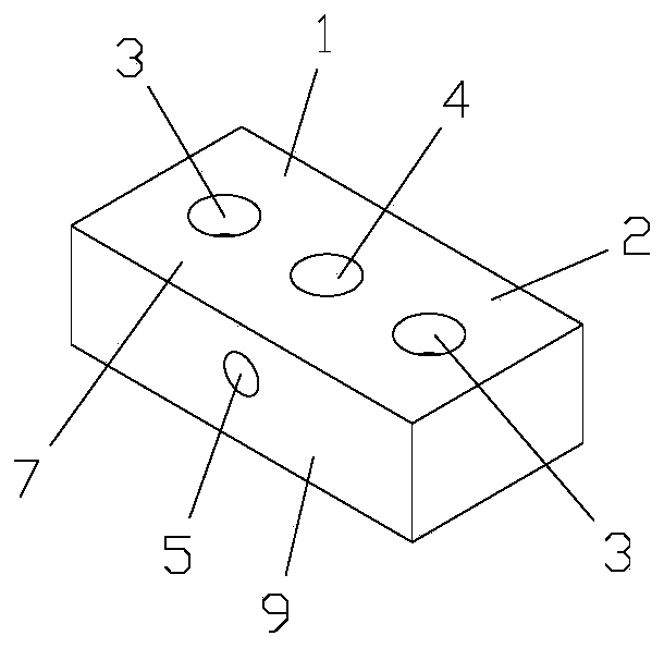
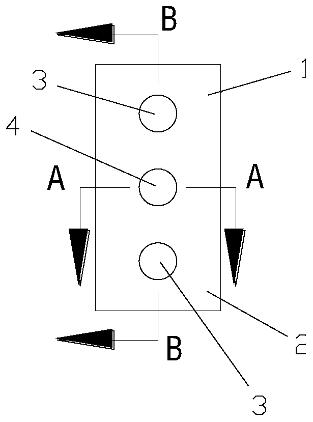
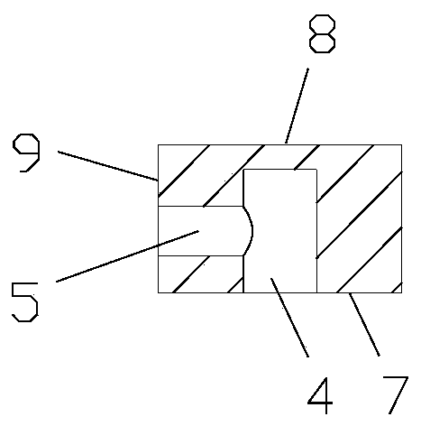
[0061] Such as Figure 1-4 As shown, this embodiment provides a capacitive coupling device, including a first dielectric resonator 1 and a second dielectric resonator 2 connected to each other, and the top surfaces of the first dielectric resonator 1 and the second dielectric resonator 2 Both are provided with tuning holes 3, the surfaces of the first dielectric resonator 1 and the second dielectric resonator 2 are provided with conductive layers, and the first dielectric resonator 1 and the second dielectric resonator 2 are provided with negative The coupling hole, the negative coupling hole includes a longitudinal blind hole 4 and a transverse blind hole 5, the inner walls of the longitudinal blind hole 4 and the transverse blind hole 5 are provided with a conductive layer. The longitudinal blind holes 4 and the transverse blind holes 5 are arranged perpendicular to each other, the longitudinal blind holes 4 are arranged perpendicular to the top surfaces 7 of the first diele...

Embodiment 2

[0063] Such as Figure 5-8 As shown, this embodiment provides a capacitive coupling device, which is basically similar in structure to the coupling device in Embodiment 1, the difference is that in this embodiment, the surface of the first dielectric resonator 1 and the second dielectric resonator 2 are arranged There is a blocking layer 6 arranged around the end face of the transverse blind hole 5 .

Embodiment 3

[0065] Such as Figure 9-12 As shown, this embodiment provides a capacitive coupling device, including a first dielectric resonator 1 and a second dielectric resonator 2 connected to each other, and the top surfaces of the first dielectric resonator 1 and the second dielectric resonator 2 Both are provided with tuning holes 3, the surfaces of the first dielectric resonator 1 and the second dielectric resonator 2 are provided with conductive layers, and the first dielectric resonator 1 and the second dielectric resonator 2 are provided with negative The coupling hole, the negative coupling hole includes a longitudinal blind hole 4 and a transverse blind hole 5, the inner walls of the longitudinal blind hole 4 and the transverse blind hole 5 are provided with a conductive layer. The longitudinal blind holes 4 and the transverse blind holes 5 are arranged perpendicular to each other, the longitudinal blind holes 4 are arranged perpendicular to the top surfaces 7 of the first diel...


PUM


Abstract

The invention discloses a capacitive coupling device and a filter. The capacitive coupling device comprises a first dielectric resonator and a second dielectric resonator which are connected with eachother, wherein a negative coupling hole is formed between the first dielectric resonator and the second dielectric resonator, the negative coupling hole comprises a longitudinal blind hole and a transverse blind hole, the longitudinal blind hole and the transverse blind hole are perpendicular to each other, the longitudinal blind hole is perpendicular to the top surfaces of the first dielectric resonator and the second dielectric resonator, and the transverse blind hole is perpendicular to the side surfaces of the first dielectric resonator and the second dielectric resonator. According to the capacitive coupling device, the two blind holes which are perpendicular to each other are formed between the two dielectric resonators to form the negative coupling hole, negative coupling between the two dielectric resonators is achieved, and the structure is simple. The structure is used in the filter, due to the fact that the area formed by the two holes is larger, a transmission zero point can be formed at the low end of a passband of the filter, the rectangular coefficient of the filter is increased, the performance of the filter is improved, and the size of the filter is reduced.

Description

technical field [0001] The invention belongs to the technical field of communication, and in particular relates to a capacitive coupling device and a filter. Background technique [0002] In the field of communication, with the development of technology, the performance requirements of filters in the system are getting higher and higher. With the improvement of requirements, the high-power microwave filter at the base station has the characteristics of high index, small size and low cost. When realizing these high-performance filters, limited by the size of the cavity, the filters need to be realized using new materials or technologies. [0003] Limited by the material characteristics of the dielectric filter, it is generally necessary to add a transmission zero point when designing the filter. Dielectric filters are more difficult to achieve capacitive cross-coupling than metal filters. Among the existing designs, Patent No. 201310688407.3 discloses three possible soluti...

Claims


Application Information

Patent Timeline
IPC IPC(8): H01P1/208
CPCH01P1/208
Inventor 刘文钟伟刚朱晖
Owner 武汉凡谷陶瓷材料有限公司
Learn More