


Quick Research
Generate reliable direction feasibility study reports for your R&D in just a few steps.

Technical Q&A
Discover and master advanced knowledge NOW. Basics, ideas, possibilities, all at once.

Find Solutions
As an expert in R&D theories, this can generate solutions to your technical problems instantly.

Evaluate Feasibility
Analyze your overall solution with one click, know your potential R&D risks in advance.

Monitor Landscape
Get weekly tech updates, stay abreast of the latest tech innovations and key insights.
Intelligent water supply device and water supply system
A technology of intelligent water supply and equipment, applied in water supply pipeline systems, water supply devices, water conservation, etc., can solve the problems of low reliability and continuous water supply capacity of water supply equipment, burnt and damaged motors of water pumps, and failure of constant flow compensators to provide continuous water supply and other issues to achieve the effect of improving reliability and continuous water supply capacity and reducing damage caused by burning
- Summary
- Abstract
- Description
- Claims
- Application Information
AI Technical Summary
Problems solved by technology
Method used
Image

Examples
Embodiment 1
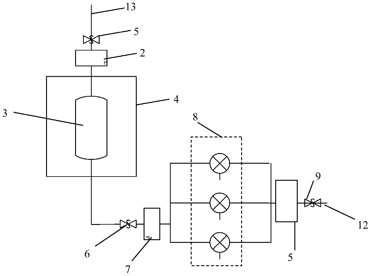
[0025] The embodiment of the present invention discloses an intelligent water supply device, including: a water inlet pipe 13, a first pressure detection module 2, a steady flow compensation tank 3, a water tank 4, a second pressure detection module 7, a pressurization module 8 and a water outlet pipe 12 ;
[0026] The steady flow compensation tank 3 is arranged inside the water tank 4, one side of the steady flow compensation tank 3 is provided with a water inlet, and the other side is provided with a water outlet, the water inlet pipe 13 is communicated with the water inlet, and the water outlet pipe 12 is communicated with the water outlet, and A first pressure detection module 2 is provided on the pipeline between the water inlet pipe 13 and the water tank 4;
[0027] One end of the pressurization module 8 is connected and communicated with the water outlet of the steady flow compensation tank 3 through a pipeline, a second pressure detection module 7 is arranged on the pi...
Embodiment 2
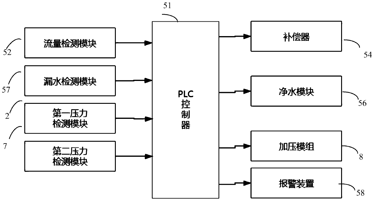
[0037] The present invention also includes a water supply control method, using the first pressure detection module 2 to detect the pressure at the water inlet to obtain the first pressure value, and using the second pressure detection module 7 to detect the pressure between the water tank and the pressurization module Get the second pressure value, use the flow detection module to detect the water flow, and use the water leakage detection module to detect whether the pipeline is leaking, and start the alarm device when water leakage occurs; when the detected first pressure value is less than the first pressure threshold, start the compensation When the detected first pressure value is greater than the first pressure threshold, the compensator will not be activated and the second pressure value will be referred to at the same time. When the second pressure value is less than the second pressure threshold and the difference between the two will be calculated. Start the pressuriz...
PUM
 Abstract
Description
Claims
Application Information
 - R&D Engineer
- R&D Manager
- IP Professional
- Industry Leading Data Capabilities
- Powerful AI technology
- Patent DNA Extraction
Browse by: Latest US Patents, China's latest patents, Technical Efficacy Thesaurus, Application Domain, Technology Topic, Popular Technical Reports.
© 2024 PatSnap. All rights reserved.Legal|Privacy policy|Modern Slavery Act Transparency Statement|Sitemap|About US| Contact US: help@patsnap.com