
Anti-overturning reinforcing device for single-pier bridge

A reinforcement device, anti-overturning technology, applied in bridge reinforcement, bridge, bridge maintenance and other directions, can solve problems such as large traffic impact, heavy workload, impact on urban planning, etc., to reduce the eccentric load on the upper part and improve the effect of stress

Inactive Publication Date: 2020-07-28
CHONGQING JIAOTONG UNIVERSITY
View PDF11 Cites 0 Cited by
  • Summary
  • Abstract
  • Description
  • Claims
  • Application Information

AI Technical Summary

Problems solved by technology

[0003] However, with the development of my country's economy, the traffic flow and vehicle load continue to increase, and the unbalanced load of overweight vehicles has led to a number of overturning and collapse accidents of single-pillar pier box girder bridges in China in recent years. Device security issues are becoming increasingly prominent
Since the single-column pier is supported by a single fulcrum in the transverse direction of the bridge, under the lateral eccentric load of the vehicle, it is not good for the lateral anti-overturning stability of the bridge. Possibly lateral overall instability of column-pier bridges
There are certain safety hazards in the bridge with single-pillar pier, but there are problems such as heavy workload, heavy traffic impact, redesign and construction of other types of bridges, and impact on urban planning. In order to prevent the tragedy of the collapse of the single-pillar bridge Repeatedly, it is necessary to strengthen the bridge with single-pillar piers to increase its ability to resist overturning

Method used


Image

  • Anti-overturning reinforcing device for single-pier bridge
  • Anti-overturning reinforcing device for single-pier bridge
  • Anti-overturning reinforcing device for single-pier bridge

Examples


Embodiment Construction

[0025] Embodiments of the present invention are described below through specific examples, and those skilled in the art can easily understand other advantages and effects of the present invention from the content described in this specification. The present invention can also be implemented or applied through other different specific implementation modes, and various modifications or changes can be made to the details in this specification based on different viewpoints and applications without departing from the spirit of the present invention. It should be noted that the diagrams provided in the following embodiments are only schematically illustrating the basic concept of the present invention, and the following embodiments and the features in the embodiments can be combined with each other in the case of no conflict.

[0026] Wherein, the accompanying drawings are for illustrative purposes only, and represent only schematic diagrams, rather than physical drawings, and should...


PUM


Abstract

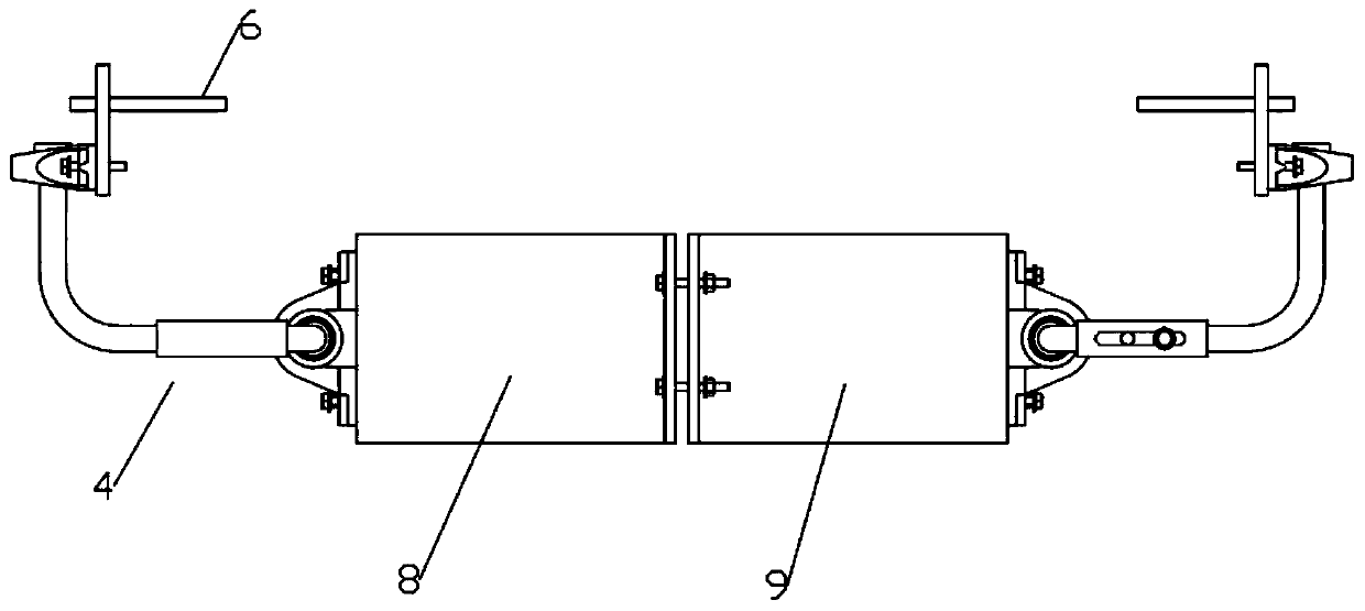
The invention discloses an anti-overturning reinforcing device for a single-pier bridge. The invention belongs to the technical field of bridge reinforcement. The device comprises a first torsion assembly and a second torsion assembly, the first torsion assembly and the second torsion assembly are the same in structure and are arranged at the two sides of a beam body respectively. Each of the first torsion assembly and the second torsion assembly comprises a torsion bar, a first connecting seat, a second connecting seat and a third connecting seat; the first torsion part and the second torsionpart are connected with a rod body through horizontal sections; the vertical section is perpendicular to the plane where the rod body is located. The vertical sections of the first torsion part and the second torsion part are fixedly connected with the first connecting base and the second connecting base respectively and connected with the side faces of two adjacent beam bodies through the firstconnecting base and the second connecting base, and the rod body is connected with the third connecting base in a pivoted mode and connected with the side face of a pier through the third connecting base. The reinforcing device can reduce influence of unbalance loading of the bridge and improve the anti-overturning capacity of the bridge.

Description

technical field [0001] The invention belongs to the technical field of bridge reinforcement devices, and in particular relates to an anti-overturning reinforcement device for single-pillar pier bridges. Background technique [0002] At present, single-pillar bridges are widely used in highway bridges because of their advantages of saving land, visual transparency, smooth lines, and beautiful appearance. And it also has the characteristics of simple and smooth appearance, occupying less space under the bridge, etc., and is equipped with a light and beautiful overall bridge, which is widely used in urban bridges and high-speed interchange ramps. [0003] However, with the development of my country's economy, the traffic flow and vehicle load continue to increase, and the unbalanced load of overweight vehicles has led to a number of overturning and collapse accidents of single-pillar pier box girder bridges in China in recent years. Device security issues are becoming increasin...

Claims


Application Information

Patent Timeline
Patent Type & Authority Applications(China)
IPC IPC(8): E01D22/00
CPCE01D22/00
Inventor 刘浪王明明
Owner CHONGQING JIAOTONG UNIVERSITY
Learn More