High-speed numerical-control circular sawing machine

A technology of circular sawing machine and sawing machine, which is applied in the direction of sawing machine, cutting tool of sawing machine, metal sawing equipment, etc., which can solve the service life of the saw blade, the surface quality of the sawing surface and the damage of the equipment itself, and reduce the feed and cutting speed of the saw blade , The saw edge is not straight, etc., to improve the running accuracy and service life, eliminate the beating of the saw blade, and achieve the effect of uniform pressure distribution

Inactive Publication Date: 2020-07-28
DONGGUAN GOODA MASCH MFG CO LTD
View PDF8 Cites 2 Cited by
  • Summary
  • Abstract
  • Description
  • Claims
  • Application Information

AI Technical Summary

Problems solved by technology

Through actual use, it is found that this pressing method is prone to vibration of the workpiece during processing, especially when sawing thin workpieces, due to the lack of rigidity of the workpiece itself, the unpressed side is more likely to produce severe vibrations, which is harmful to the saw blade. The service life, the surface quality of the sawing surface and the equipment itself all bring great damage, so the feed and cutting speed of the saw blade have to be reduced, which greatly reduces the working efficiency of the equipment
[0003] And for a long time, sawing machines generally have problems such as small processing range, slow speed, uneven saw edge, rough sawing surface, and cumbersome operation.

Method used


Image

  • High-speed numerical-control circular sawing machine
  • High-speed numerical-control circular sawing machine
  • High-speed numerical-control circular sawing machine

Examples


Embodiment 1

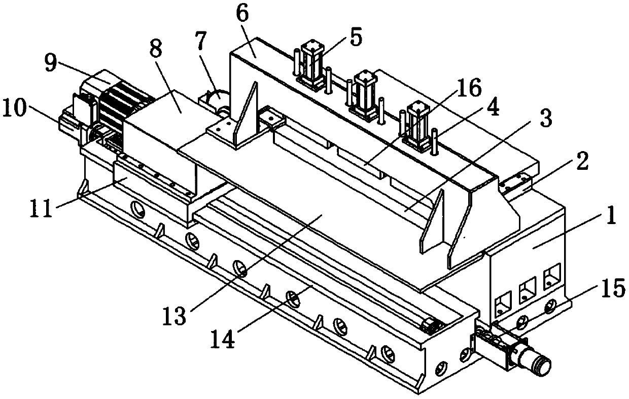
[0028] Embodiment 1: refer to Figure 1-4 , a high-speed numerical control circular sawing machine, comprising a sawing machine frame 1, a sawing machine holder 14, a workpiece clamping mechanism and a spindle feed mechanism, the workpiece clamping mechanism is arranged on the top of the sawing machine frame 1, and the spindle feed mechanism is arranged on The top of the sawing machine holder 14;

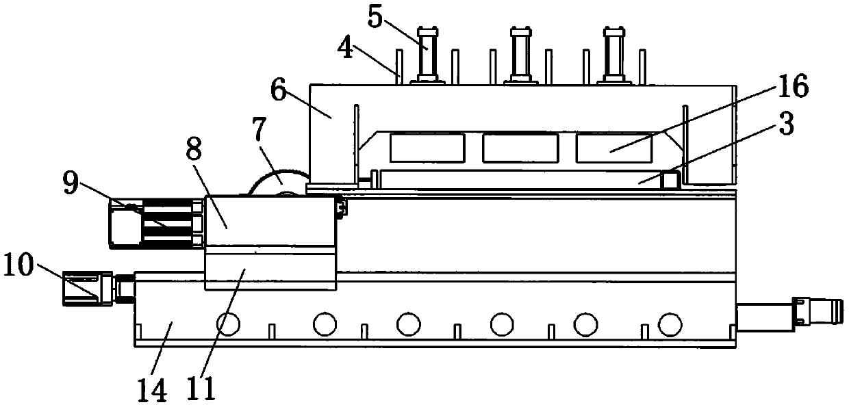
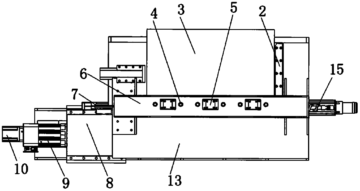
[0029] The workpiece clamping mechanism includes an oil cylinder 5, a pressure plate 16, a discharge plate 3 and a positioning reference block 2, and the workpiece clamping mechanism is installed on the steel gantry 6, and the steel gantry 6 is bolted to the sawing machine frame 1 , and the bottom of the steel gantry 6 is also bolted with a workbench plate 13;

[0030] The steel gantry 6 is provided with three oil cylinders 5 arranged in a row, and the bottom of the oil cylinders 5 is connected on the pressure plate 16, the bottom side of the pressure plate 16 is correspondingly pr...

Embodiment 2

[0037] Embodiment 2: refer to Figure 1-4 , a high-speed numerical control circular sawing machine, comprising a sawing machine frame 1, a sawing machine holder 14, a workpiece clamping mechanism and a spindle feed mechanism, the workpiece clamping mechanism is arranged on the top of the sawing machine frame 1, and the spindle feed mechanism is arranged on The top of the sawing machine holder 14;

[0038] The workpiece clamping mechanism includes an oil cylinder 5, a pressure plate 16, a discharge plate 3 and a positioning reference block 2, and the workpiece clamping mechanism is installed on the steel gantry 6, and the steel gantry 6 is bolted to the sawing machine frame 1 , and the bottom of the steel gantry 6 is also bolted with a workbench plate 13;

[0039] The spindle feed mechanism includes a reducer 9, a gearbox 8, a saw blade 7, a saw head sliding seat 11 and an output spindle, and the saw head sliding seat 11 is slidably fitted on the sawing machine fixing seat 14;...


PUM


Abstract

The invention discloses a high-speed numerical-control circular sawing machine which comprises a sawing machine frame, a sawing machine fixing base, a workpiece clamping mechanism and a main shaft feeding mechanism. The workpiece clamping mechanism is arranged at the upper portion of the sawing machine frame. The main shaft feeding mechanism is arranged at the upper portion of the sawing machine fixing base. A ball screw controlled by a drive motor to be operated is arranged between the sawing machine frame and the sawing machine fixing base. The workpiece clamping mechanism comprises oil cylinders, a pressing plate, a discharging plate and a positioning reference block, and the workpiece clamping mechanism is installed on a steel part portal frame. The main shaft feeding mechanism comprises a speed reducer, a gearbox, a saw blade, a saw head sliding base and an output main shaft. The three evenly-distributed oil cylinders are arranged on an oil cylinder portal frame. The pressing plate is controlled by the pressure of the oil cylinders to act on the workpiece, so that the pressure acting on the workpiece is evenly distributed. The workpiece is clamped firmly, and it is ensured that the sawed workpiece is stable and does not vibrate.

Description

technical field [0001] The invention relates to the field of numerical control processing equipment, in particular to a high-speed numerical control circular sawing machine. Background technique [0002] GD1510 circular saw adopts gantry structure for workpiece compression, and presses the workpiece through the downward pressure cylinder. In the past, when the sawing machine used the downward pressure method to compress the workpiece, it was generally one-sided compression, that is, the downward force only acts on the saw edge of the workpiece. One side, while the other side is free. Through actual use, it is found that this pressing method is prone to vibration of the workpiece during processing, especially when sawing thin workpieces, due to the lack of rigidity of the workpiece itself, the unpressed side is more likely to produce severe vibrations, which is harmful to the saw blade. The service life, the surface quality of the sawing surface and the equipment itself all ...

Claims


Application Information

Patent Timeline
Patent Type & Authority Applications(China)
IPC IPC(8): B23D47/04B23D47/12B23D61/10
CPCB23D47/04B23D47/12B23D61/10
Inventor 凌益民黄朋飞
Owner DONGGUAN GOODA MASCH MFG CO LTD
Why Eureka
Try Eureka