A multi-station stamping equipment

A stamping equipment and multi-station technology, applied in the field of stamping, can solve the problems of large-scale punching of unfavorable parts, poor safety, and inability to accurately position multiple stations, so as to achieve high punching efficiency, high safety, and high efficiency The effect of production

Inactive Publication Date: 2020-12-11
揭阳市三泰五金实业有限公司
View PDF9 Cites 1 Cited by
  • Summary
  • Abstract
  • Description
  • Claims
  • Application Information

AI Technical Summary

Problems solved by technology

[0004] The purpose of the present invention is to provide a multi-station stamping equipment to at least solve the problems that the existing technology cannot accurately position multi-stations, has poor safety, and is not conducive to large-scale punching of parts and components.

Method used


Image

  • A multi-station stamping equipment
  • A multi-station stamping equipment
  • A multi-station stamping equipment

Examples


Embodiment Construction

[0030] The following will clearly and completely describe the technical solutions in the embodiments of the present invention with reference to the accompanying drawings in the embodiments of the present invention. Obviously, the described embodiments are only some, not all, embodiments of the present invention. Based on the embodiments of the present invention, all other embodiments obtained by persons of ordinary skill in the art without making creative efforts belong to the protection scope of the present invention.

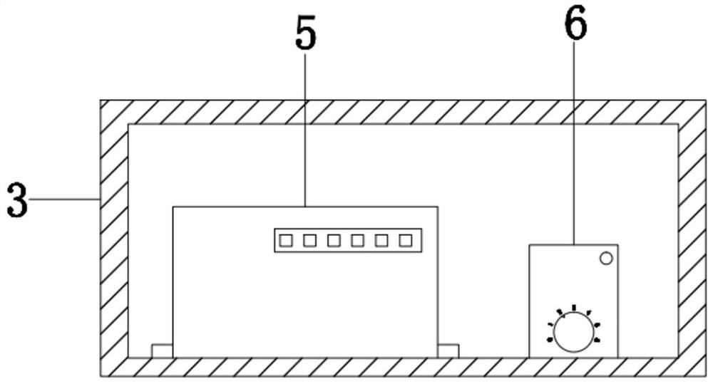
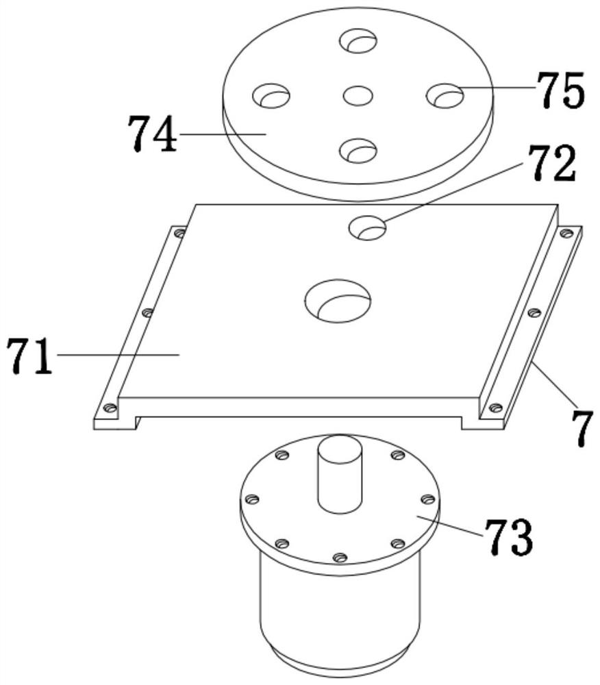
[0031] see Figure 1-6 , the present invention provides a technical solution: a multi-station stamping equipment, including a workbench 1, a support leg 2, a box body 3, a button 4, a PLC controller 5, a delay relay 6, a rotating mechanism 7, and a clamping assembly 8 and stamping mechanism 9, the four supporting legs 2 are respectively fixedly connected to the four corners of the bottom of the workbench 1, the box body 3 is detachably arranged on the bottom f...


PUM


Abstract

The invention discloses multi-position punching equipment. The multi-position punching equipment comprises a working table, four supporting legs, a box, a button, a PLC, a time-delay relay, a rotatingmechanism and clamping assemblies, wherein the four supporting legs are fixedly connected to the four corners of the bottom of the working table; the box is detachably arranged on the front side of the bottom of the working table; the button is detachably arranged on the front side of the box; the PLC and the time-delay relay are connected to the left right and the right side of the bottom of aninner cavity of the box through screws correspondingly; the time-delay relay and the button are both electrically connected with the PLC; the rotating mechanism is connected to the bottom of the working table through screws, and the box is located on the front side of the rotating mechanism; and the four clamping assemblies are connected to the top of the rotating mechanism clockwise at intervalsof 90 degrees. The multi-position punching equipment can realize multi-position positioning of parts in the punching process and ensure the punching quality, is high in safety, suitable for large-scale punching of the same kind of parts and high in punching efficiency and greatly meets the requirement for high-efficiency production.

Description

technical field [0001] The invention relates to the technical field of stamping, in particular to a multi-station stamping equipment. Background technique [0002] A punch press is a stamping press. In national production, the stamping process has the advantages of saving materials and energy, high efficiency, low technical requirements for operators, and the ability to produce products that cannot be achieved by mechanical processing through various mold applications. It is used more and more widely. Punching machines are widely used in stamping and forming of electronics, communications, computers, household appliances, furniture, transportation (automobiles, motorcycles, bicycles) hardware parts, etc.; [0003] According to the material and size of the parts, it is necessary to choose a suitable punching machine, or even a targeted special punching machine. At present, for punching some small parts, small punching equipment such as pneumatic and electric are mostly used...

Claims


Application Information

Patent Timeline
Patent Type & Authority Patents(China)
IPC IPC(8): B21D28/24B21D43/00
CPCB21D28/24B21D43/003
Inventor 蒋军华
Owner 揭阳市三泰五金实业有限公司
Why Eureka
Try Eureka