An electromagnetic-fluid impact composite forming device and forming method for pipe fittings

A technology of composite forming and pipe fittings, which is applied in the field of material processing and forming, can solve the problems of difficult to achieve precise shape control of parts, difficult to control the forming process, fast deformation speed, etc., and achieve the effect of improving forming efficiency and increasing forming limit

Active Publication Date: 2022-05-27
CENT SOUTH UNIV
View PDF11 Cites 0 Cited by
  • Summary
  • Abstract
  • Description
  • Claims
  • Application Information

AI Technical Summary

Problems solved by technology

However, in traditional electromagnetic forming, the deformation speed of pipe fittings under the action of electromagnetic force is too fast, which makes it difficult to control the forming process and achieve precise shape control of parts.

Method used


Image

  • An electromagnetic-fluid impact composite forming device and forming method for pipe fittings
  • An electromagnetic-fluid impact composite forming device and forming method for pipe fittings
  • An electromagnetic-fluid impact composite forming device and forming method for pipe fittings

Examples


Embodiment 1

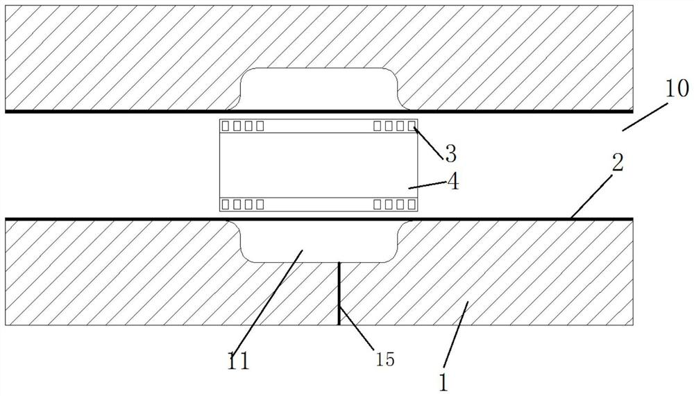
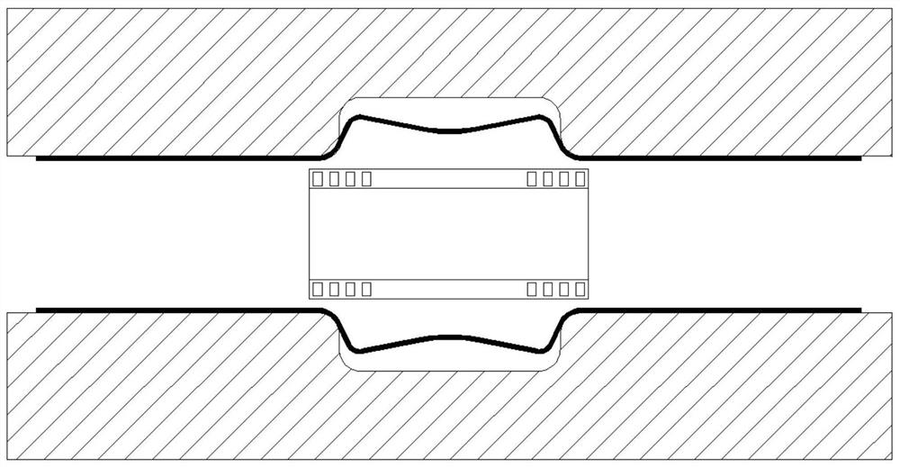
[0039] like Figure 1-5 As shown, the embodiment of the present invention firstly discloses an electromagnetic-fluid impact composite forming device for pipe fittings, comprising a mold 1, wherein a forming hole 10 that can fit the outer wall of the pipe fitting 2 is provided in the mold 1, and the side wall of the forming hole 10 is provided with a forming hole 10. A forming cavity 11 is provided. During the forming process, the inner side wall of the pipe fitting 2 will receive electromagnetic force to expand outward, and finally fit with the bottom surface of the forming cavity 11. The forming cavity 11 is provided with an outwardly penetrating air hole 15 for the pipe fitting. When the wall is expanded outwardly by electromagnetic force, there is exhaust gas. The forming hole 10 is provided with a bulging coil 3 that is installed in the pipe fitting 2 and is opposite to the forming cavity 11. The bulging coil 3 is an electromagnetic forming coil, and at least One side is d...

Embodiment 2

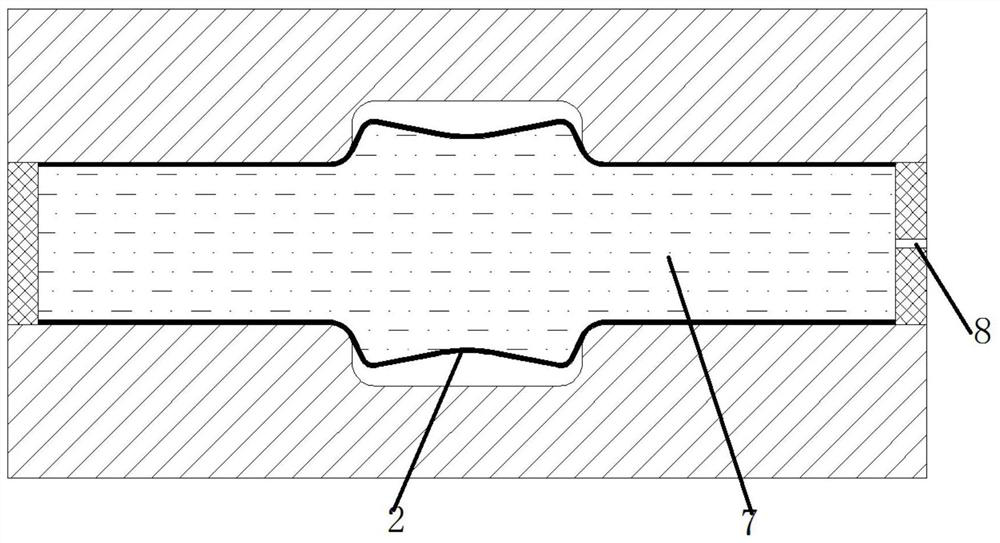
[0043] like Figure 6-9As shown, the electromagnetic-fluid impact composite forming device for pipe fittings according to the embodiment of the present invention is basically the same as that of the first embodiment, except that the sealing member includes a first push block 5 and a second push block 6 made of metal, The first push block 5 and the second push block 6 are sealed and slid on both ends of the forming hole 10 respectively, and a side push coil 9 is provided on the outer side of at least one of the first push block and the second push block 6. In this embodiment Among them, the outer side of the first push block 5 and the second push block 6 are provided with a side push coil 9, and the side push coil 9 is an electromagnetic forming coil, so that when the fluid injection hole 8 is injected with fluid, it can be sealed The pressure exerted by the coil 9 on the first push block 5 and the second push block 6 squeezes the fluid 7, thereby driving the tube 2 to deform a...


PUM


Abstract

The invention discloses an electromagnetic-fluid impact composite forming device for pipe fittings and a forming method thereof. The forming device includes a mold, and a forming hole capable of fitting the pipe fitting is arranged in the mold, and a forming cavity is arranged on the side wall of the forming hole. The forming hole is provided with a bulging coil for installation in the pipe fitting and opposite to the forming cavity, at least one side of the forming hole is detachably provided with a seal for sealing the forming hole, and the sealing is provided for injecting into the forming hole Fluid injection hole for fluid. The present invention combines the advantages of high precision of fluid forming, high rate of electromagnetic forming and easy installation of coils according to deformation needs, and can realize high-precision deformation of difficult-to-deform areas of difficult-to-deform materials (such as aluminum alloys, magnesium alloys, titanium alloys, etc.) .

Description

technical field [0001] The invention relates to the technical field of material processing and forming, in particular to an electromagnetic-fluid impact composite forming device for pipe fittings and a forming method thereof. Background technique [0002] The fluid forming technology of pipe fittings usually uses the pipe blank as the raw material, and by applying fluid pressure to the lumen, plastic deformation occurs in the cavity of the given mold, and the pipe wall is attached to the inner surface of the mold to obtain the desired shape parts. Technology. Compared with traditional forming, fluid forming parts have good surface quality and high dimensional accuracy, and are now widely used in the forming of parts in the fields of automobiles, aviation and aerospace. However, the fluid forming speed is slow and it is a low-rate forming method. In addition, during the forming process, the fluid force received by different areas of the pipe fitting is evenly distributed, a...

Claims


Application Information

Patent Timeline
Patent Type & Authority Patents(China)
IPC IPC(8): B21D26/14B21D26/047B21D26/045
CPCB21D26/14B21D26/047B21D26/045
Inventor 崔晓辉颜子钦夏雯桢喻海良黄长清代鹏逸
Owner CENT SOUTH UNIV
Why Eureka
Try Eureka