Eureka AIR delivers breakthrough ideas for toughest innovation challenges, trusted by R&D personnel around the world.

Threading sealing structure of ultrasonic transducer

A technology of ultrasonic transducer and sealing structure, which is applied in the sealing of engines, medical science, pipes, etc., can solve the problems of open circuit, not being large enough, conductive metal rings and plastic parts not being well sealed, etc., to improve the safety factor, To ensure the effect of normal transmission

Pending Publication Date: 2020-07-24
天津越安医疗科技有限公司
View PDF0 Cites 4 Cited by
  • Summary
  • Abstract
  • Description
  • Claims
  • Application Information

AI Technical Summary

Problems solved by technology

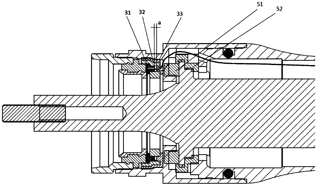
[0004] The manual control wire in the transducer housing of the existing ultrasonic knife transmits the manual control signal from the conductive metal ring at one end of the transducer housing to the ultrasonic knife generator, and the manual control wire is connected between the conductive metal ring and the cable To pass through a plastic inner hole, a rubber inner hole, and the inner hole on the transducer housing in turn, and then connect to the cable through the inner cavity of the transducer housing, firstly, the rubber parts will be damaged during the assembly of the housing. Due to the limitation of deformation and reprocessing space, the three inner holes mentioned above cannot be large enough, so that the outer layer of the hard part and the manual control wire will be damaged or even broken when it contacts with the plastic part and the transducer shell. Opening will result in a short circuit or open circuit between the manual control wire and the transducer shell. Secondly, the conductive metal ring and the plastic part cannot be sealed well, and water will enter the shell, which will also cause a short circuit between the manual control wire and the transducer shell. The results of the above two points It will cause the failure of manual signal transmission, and also cause the ultrasonic scalpel to be unable to be activated during the operation.

Method used


Image

  • Threading sealing structure of ultrasonic transducer
  • Threading sealing structure of ultrasonic transducer
  • Threading sealing structure of ultrasonic transducer

Examples


Embodiment Construction

[0021] In order to enable those skilled in the art to better understand the technical solutions of the present invention, the present invention will be further described in detail below in conjunction with the accompanying drawings and preferred embodiments.

[0022] As shown in the figure, the present invention includes a transducer housing 1, a conductive ring assembly 2, a threading sealing assembly 3, a manual control wire 4 and a transducer clamping assembly 5, and the transducer housing 1 includes at least a first segment housing 11 and the second segment housing 12 , the conductive ring assembly 2 includes an outer conductive ring 21 , an insulator 22 and an inner conductive ring 23 . The outer conductive ring 21 and the inner conductive ring 23 transmit manual control signals, and the insulator 22 isolates and insulates the outer conductive ring 21 and the inner conductive ring 23 . The threading seal assembly 3 includes a front flexible seal 31, a rigid support body 3...


PUM


Abstract

The invention relates to the field of ultrasonic surgical operating instruments and especially relates to a threading sealing structure of an ultrasonic transducer. A manual control wire starts from ajoint of the manual control wire and an inner conducting ring and successively passes through straight slots of a front flexible sealing piece, a middle rigid supporting body, a rear flexible sealingpiece and a transducer shell; the parts, penetrating through the above elements, of the manual control wire are surrounded by the surfaces of the flexible elements; damage such as outer layer skin breaking and falling off caused by friction between the manual control wire and the elements is avoided; short circuit or open circuit between the manual control wire and the transducer shell due to disconnection can be avoided too; and the joint of the manual control wire and the inner conducting ring and the position, penetrating through the transducer shell, of the manual control wire are both covered and sealed by the flexible element, short circuit between the manual control wire and the transducer shell due to water inflow is avoided, a safety coefficient is increased, normal transmissionof manual control signals is guaranteed, and an ultrasonic scalpel is activated smoothly.

Description

technical field [0001] The invention relates to the field of ultrasonic surgical instruments, in particular to an ultrasonic transducer threading sealing structure. Background technique [0002] Now, the ultrasonic scalpel has been widely used in clinical surgical treatment. The ultrasonic scalpel is generally composed of an ultrasonic scalpel generator, a transducer, a cable, and a scalpel head with a manual switch. Activate the manual switch on the scalpel head to make the ultrasonic scalpel At this time, the host outputs a high-frequency resonance electrical signal to the transducer, and then the transducer converts the high-frequency vibration signal into a high-frequency mechanical vibration and sends it to the scalpel head, and the scalpel head amplifies the high-frequency machinery to act on the tissue , to vaporize water in tissue cells, break protein hydrogen bonds, disintegrate cells, cut tissue or coagulate blood, so as to achieve the purpose of tissue cutting and...

Claims


Application Information

Patent Timeline
Patent Type & Authority Applications(China)
IPC IPC(8): H02G3/22F16L5/02F16J15/06A61B17/32
CPCA61B17/320068F16J15/06F16L5/02H02G3/22
Inventor 孙秋香任忠政
Owner 天津越安医疗科技有限公司
Why Eureka
Eureka Blog
Learn More