
Method for controlling ultralow emission of sintering flue gas

A sintering flue gas, ultra-low technology, applied in the steam generation method, separation method, chemical instrument and method using heat carrier, etc., can solve the problem of large investment cost and operating cost, high cost, large investment in activated carbon desulfurization and denitrification operation, etc. problems, to achieve the effect of reducing system cost, increasing waste heat power generation, and improving application prospects

Pending Publication Date: 2020-07-24
MAANSHAN IRON & STEEL CO LTD
View PDF0 Cites 0 Cited by
  • Summary
  • Abstract
  • Description
  • Claims
  • Application Information

AI Technical Summary

Problems solved by technology

[0003] Activated carbon desulfurization and denitrification operation requires a large investment and high cost; thermal power coal-fired power plants generally use wet SNCR+SCR ammonia denitration and desulfurization for ultra-low emission technologies. These technologies do not make full use of the characteristics of sintering flue gas and the temperature of sintering flue gas. Sintering flue gas preheating, large investment and operating costs

Method used


Image

  • Method for controlling ultralow emission of sintering flue gas
  • Method for controlling ultralow emission of sintering flue gas

Examples


Embodiment approach 1

[0028] Embodiment 1 The sintering fan of a 380m2 sintering machine is 2×1.2 million m3 / h, the utilization factor is 1.23t / m2·h, the fan with cooling machine is 7×260,000 m3 / h, the thickness of the material layer is 900mm, and the temperature of the bellows of the sintering machine is as follows The bellows under each trolley are double-row bellows (south side, north side), and there is a bellows branch pipe under each bellows box to connect the large flue to double flue, and double fans are arranged. The recyclable heat air box is the first 3 belt cooler fans, and the average temperature of the waste heat power generation system is 385°C. The average emission concentration of SO2 and NOX in the sintering flue gas is 228mg / Nm3 and 180mg / Nm3 respectively, (the current standard of SO2 and NOX is 300mg / Nm3 and 200mg / Nm3), the power generation per ton of ore in the early stage is 10.71kWh / t ore, without the denitrification system, only the desulfurization cost is 10 yuan / t ore.

[...

Embodiment approach 2

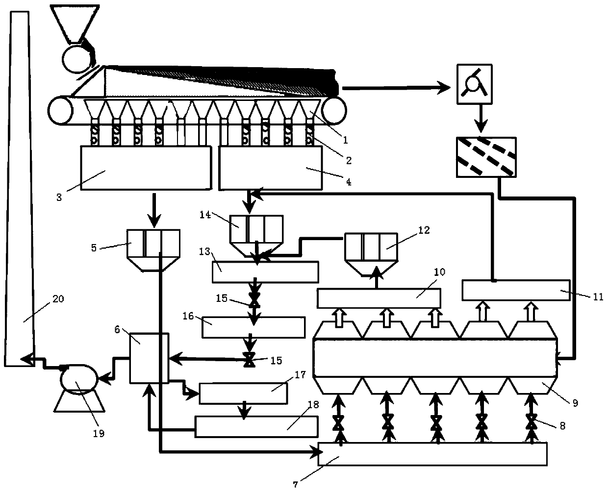
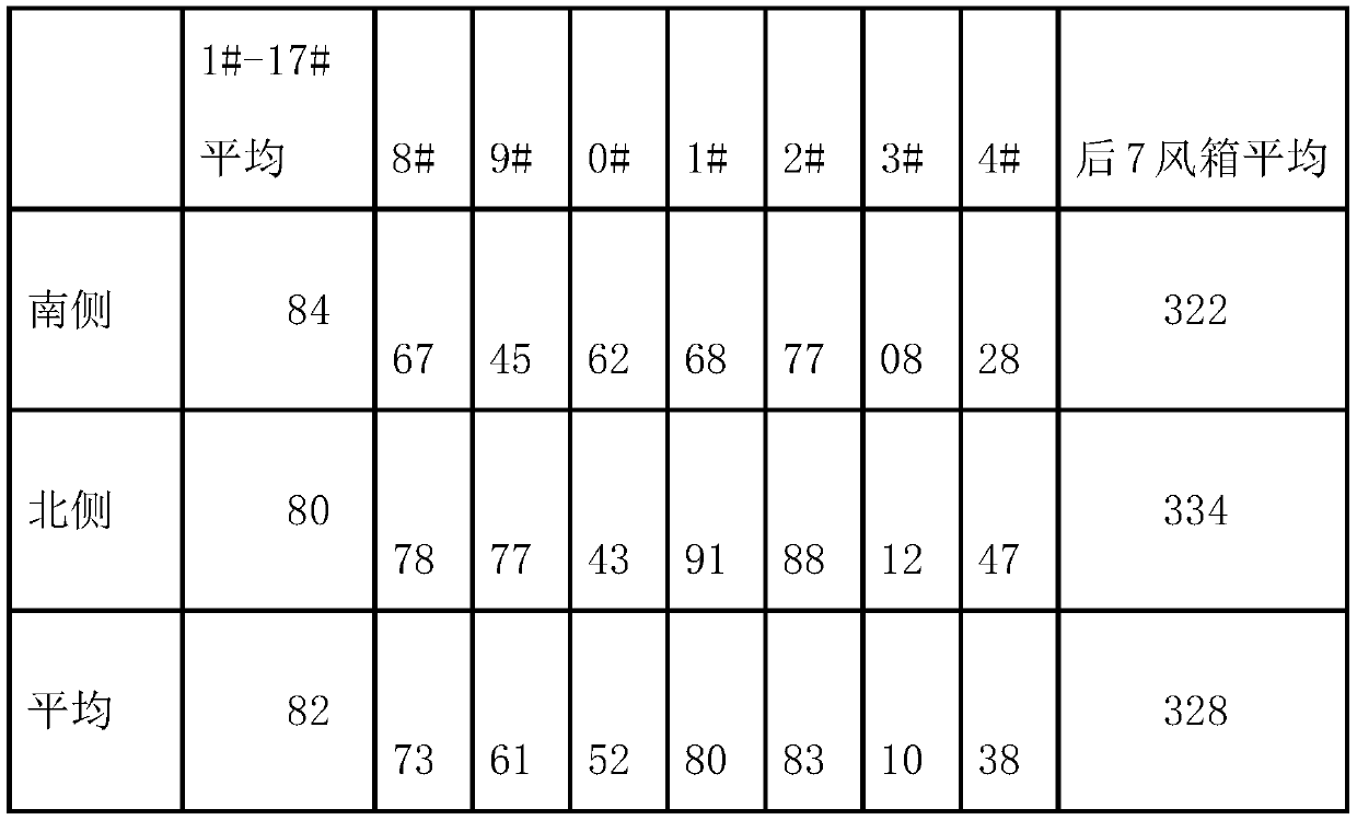
[0032]Embodiment 2 A 2×435m2 sintering machine, the main exhaust fan of a single sintering machine is 2×1.5 million m3 / h, the utilization coefficient is 1.3t / m2·h, the fan with cooling machine is 5×420,000 m3 / h, the sintering machine There are 26 bellows, the average temperature of the first 17 bellows is 85°C, and the average temperature of the last 9 bellows is 325°C. The cost of a sintering machine using activated carbon for desulfurization and denitrification is 19.8 yuan / t ore. 360℃, waste heat power generation is 9.6kWh / t mine. The other sintering machine adopts this technology. The cooling of the sintering zone requires an air volume of 2.2 million m3 / h, and the low-temperature sintering flue gas volume is 1.96 million m3 / h, which requires 240,000 m3 / h of air for cooling. The first four are equipped with cooling fans to generate electricity , the intake temperature is 340°C, the waste heat power generation is 16.2kWh / t mine, and the electricity price is 0.5 yuan / kWh, th...


PUM


Abstract

The invention discloses a method for controlling ultralow emission of sintering flue gas. The method is characterized by comprising steps as follows: low-temperature sintering flue gas in a large coldair flue is introduced into a sintering ore cooling system, the temperature of the sintering flue gas is increased through sintering ore sensible heat, then the heated flue gas is introduced into a waste heat power generation system, and the flue gas obtained after power generation is subjected to desulfurization and denitrification and then is discharged out of a chimney through a main exhaust fan. According to the method for controlling ultralow emission of the sintering flue gas, the cost of a sintering flue gas emission reduction system can be reduced, the waste heat power generation capacity of the sintering machine is increased, and good application prospects are achieved.

Description

technical field [0001] The invention belongs to the technical field of sintering production, and more specifically relates to a method for controlling ultra-low emission of sintering flue gas. Background technique [0002] The Ministry of Ecology and Environment revised the emission limits of sintering head flue gas, pellet roasting flue gas particulate matter, sulfur dioxide, and nitrogen oxides from 20mg / m3, 50mg / m3, 100mg / m3 to 10mg / m3, 35mg / m3, and 50mg / m3 m3 All qualified iron and steel enterprises will complete ultra-low emission transformation by region in 2020, 2022, and 2025. Relevant experts pointed out that the ultra-low emission transformation technology of steel sintering machine heads is very mature, adopting the technical route centered on the integrated process of activated carbon desulfurization and denitrification or adopting the technical route centered on the ultra-low emission technology of thermal power coal-fired power plants. The paths are all very m...

Claims


Application Information

Patent Timeline
Patent Type & Authority Applications(China)
IPC IPC(8): F27D17/00F22B1/18B01D53/81B01D53/50B01D53/86B01D53/56B01D50/00
CPCB01D50/00B01D53/508B01D53/56B01D53/81B01D53/8628B01D2258/025B01D2258/0283F22B1/18F27D17/004F27D17/008F27D2017/006
Inventor 陈东峰李帮平李小静张晓萍熊德怀武轶朱贺民
Owner MAANSHAN IRON & STEEL CO LTD
Learn More