
Movable inertia guiding control device

A technology of oriented control and inertia, applied in the direction of elastic suspension, transportation and packaging, shock absorbers, etc., to achieve the effect of state switching conditions, high degree of integration, and reasonable state switching conditions

Active Publication Date: 2020-07-24
JIANGSU UNIV
View PDF20 Cites 2 Cited by
  • Summary
  • Abstract
  • Description
  • Claims
  • Application Information

AI Technical Summary

Problems solved by technology

Different from the damper, the force at the two ends of the damper is related to the relative speed of the two ends, while the force at the two ends of the dynamic inertial element is related to the relative acceleration of the two ends, which is different from the speed of motion that is easy to identify the direction. The direction is difficult to be directly identified by the direction of motion of the object, so some "on-off" control methods are difficult to apply to dynamic inertial components in a passive way

Method used


Image

  • Movable inertia guiding control device
  • Movable inertia guiding control device
  • Movable inertia guiding control device

Examples


Embodiment Construction

[0030] Embodiments of the present invention are described in detail below, examples of which are shown in the drawings, wherein the same or similar reference numerals designate the same or similar elements or elements having the same or similar functions throughout. The embodiments described below by referring to the figures are exemplary and are intended to explain the present invention and should not be construed as limiting the present invention.

[0031] In describing the present invention, it is to be understood that the terms "central", "longitudinal", "transverse", "length", "width", "thickness", "upper", "lower", "axial", The orientation or positional relationship indicated by "radial", "vertical", "horizontal", "inner", "outer", etc. is based on the orientation or positional relationship shown in the drawings, and is only for the convenience of describing the present invention and simplifying the description , rather than indicating or implying that the device or elem...


PUM


Abstract

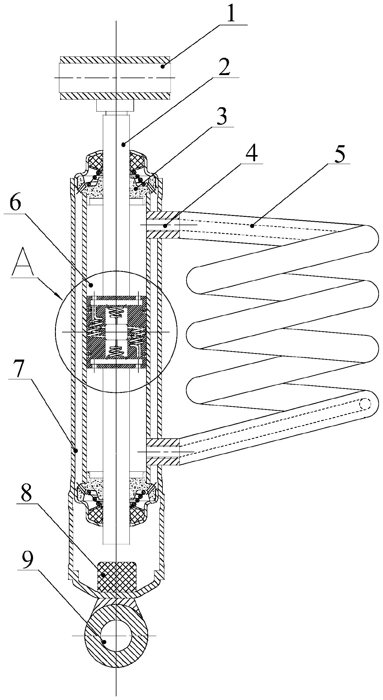
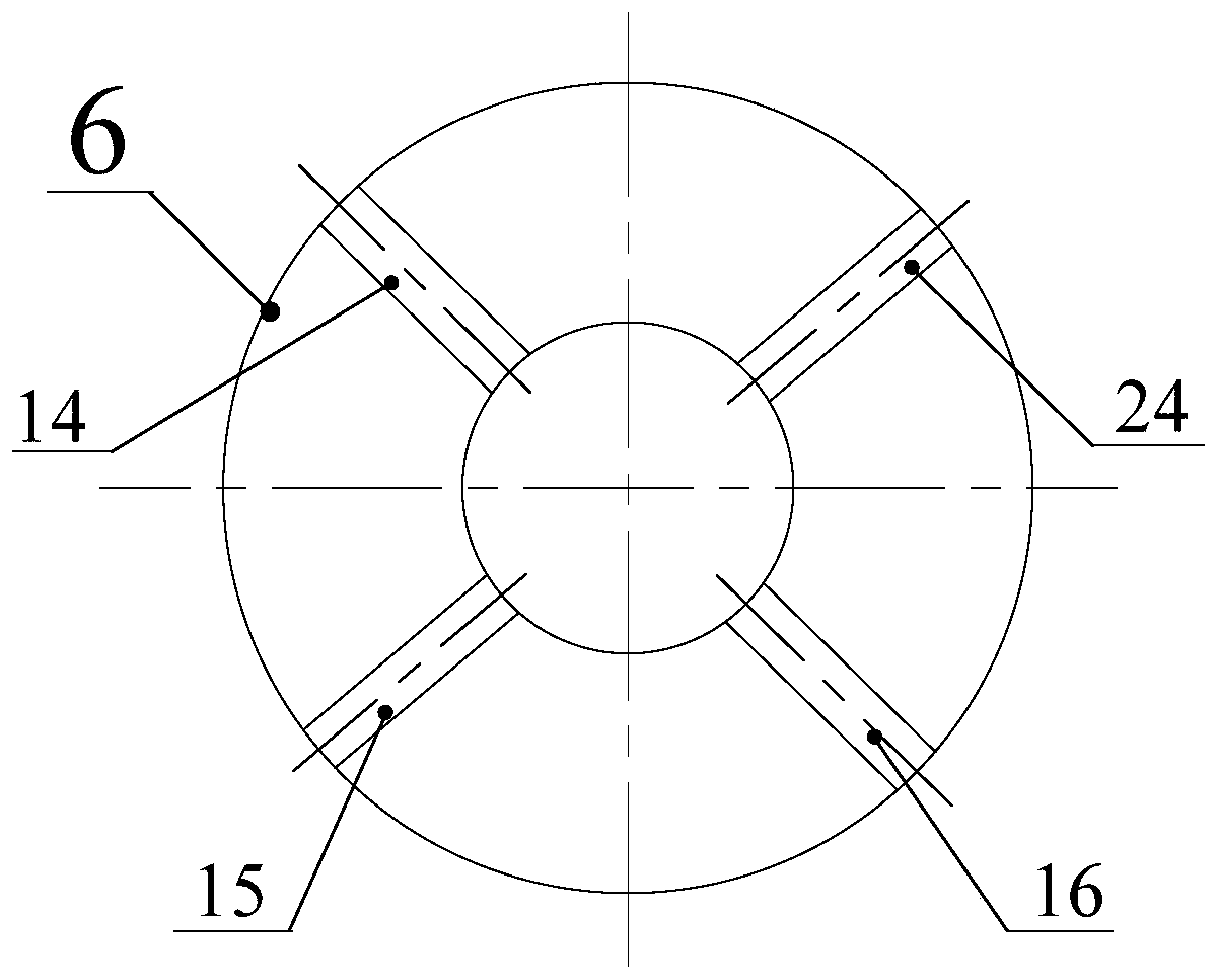
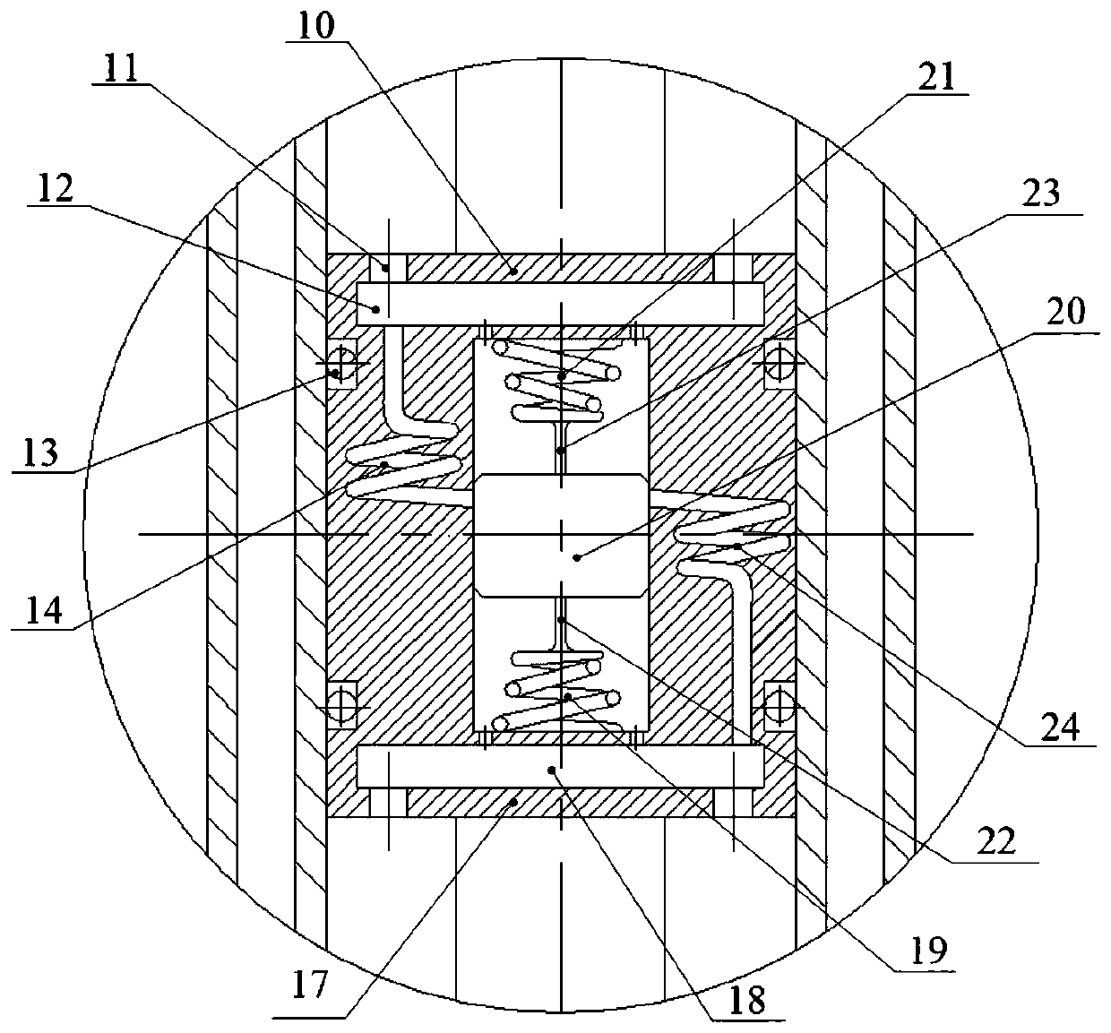
The invention provides a movable inertia guiding control device which comprises a cylinder block, a piston and a main helical pipe; the piston divides the cavity of the cylinder block into an upper cavity and a lower cavity; the main helical pipe is connected between the upper cavity and the lower cavity; the piston comprises a piston main body, a mass block and a plurality of spiral grooves; a cavity is formed in the piston main body and communicates with the upper cavity and the lower cavity separately; the two ends of the mass block are mounted in the cavity through elastic devices; the spiral grooves uniformly formed along the cavity are formed in the piston main body; a part of spiral grooves communicates with the upper cavity and the cavity; the other part of spiral grooves communicates with the lower cavity and the cavity; and according to variation of the accelerated speed, the mass block selectively enables the spiral grooves to communicate with or block the cavity. The movable inertia guiding control device realizes identification and follow-up control of the accelerated speed directions at two endpoints, so that the semi-active control method based on the accelerated speed is realized passively, and input of external end energy is not needed. In addition, the movable inertia guiding control device is high in degree of integration and is easy to arrange.

Description

technical field [0001] The invention relates to the field of motor vehicle shock absorbers, in particular to a dynamic inertia guidance control device. Background technique [0002] With the development of my country's transportation industry, domestic passenger vehicles are developing in the direction of intelligence, high speed, light weight and cleanliness, and the requirements for energy saving of vehicles are getting higher and higher. With the consolidation of the vehicle suspension structure, the improvement of the comprehensive performance of ordinary passive suspension is approaching the limit, and researchers are gradually turning their attention to semi-active control suspension and active control suspension. However, no matter semi-active control suspension or active control suspension, energy input outside the suspension is required to achieve control, and the development of active suspension is slow because of high energy consumption. [0003] With the develop...

Claims


Application Information

Patent Timeline
Patent Type & Authority Applications(China)
IPC IPC(8): F16F9/18F16F9/19F16F9/32F16F9/34B60G17/08
CPCF16F9/18F16F9/19F16F9/3207F16F9/34B60G17/08F16F7/1034F16F9/20F16F9/3405F16F9/504
Inventor 杨艺陈龙刘昌宁杨晓峰沈钰杰
Owner JIANGSU UNIV
Learn More