
A device for passive realization of acceleration control

An acceleration control, moving block technology, used in transportation and packaging, shock absorbers, mechanical equipment, etc.

Active Publication Date: 2021-09-10
JIANGSU UNIV
View PDF19 Cites 0 Cited by
  • Summary
  • Abstract
  • Description
  • Claims
  • Application Information

AI Technical Summary

Problems solved by technology

Different from the damper, the force at the two ends of the damper is related to the relative speed of the two ends, while the force at the two ends of the dynamic inertial element is related to the relative acceleration of the two ends, which is different from the speed of motion that is easy to identify the direction. The direction is difficult to distinguish directly through the direction of motion of the object, so some "ON-OFF" control methods are difficult to be applied to dynamic inertial components by passive implementation methods

Method used


Image

  • A device for passive realization of acceleration control
  • A device for passive realization of acceleration control
  • A device for passive realization of acceleration control

Examples


Embodiment Construction

[0028] The present invention is made in conjunction with the accompanying drawings and specific examples, but the scope of the invention is not limited thereto.

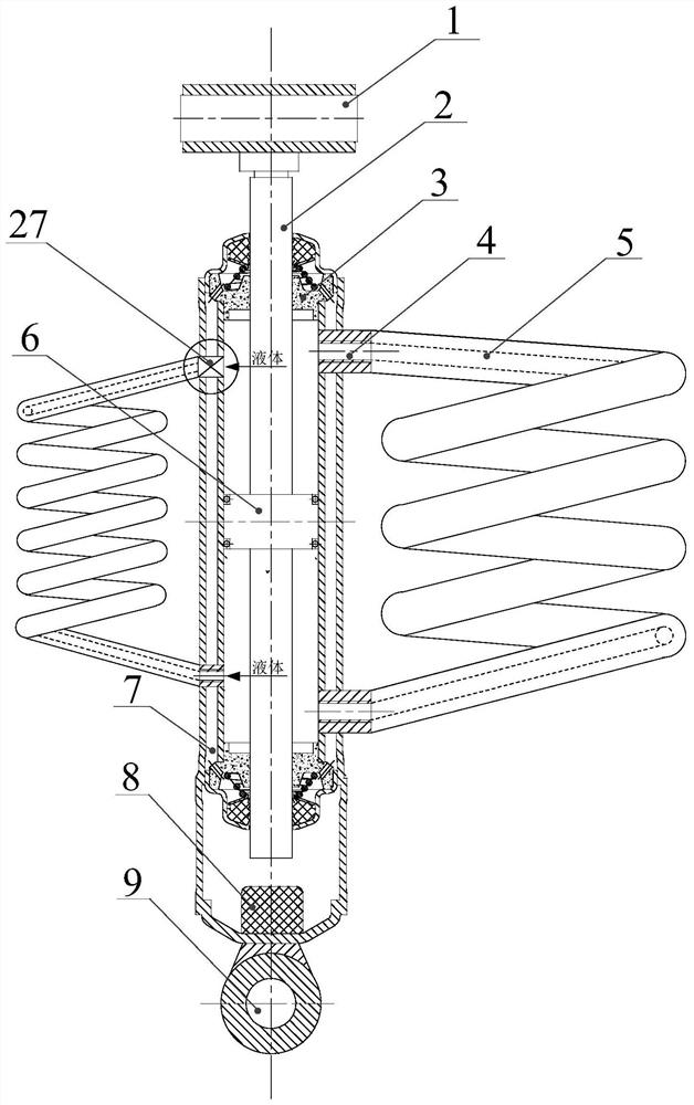
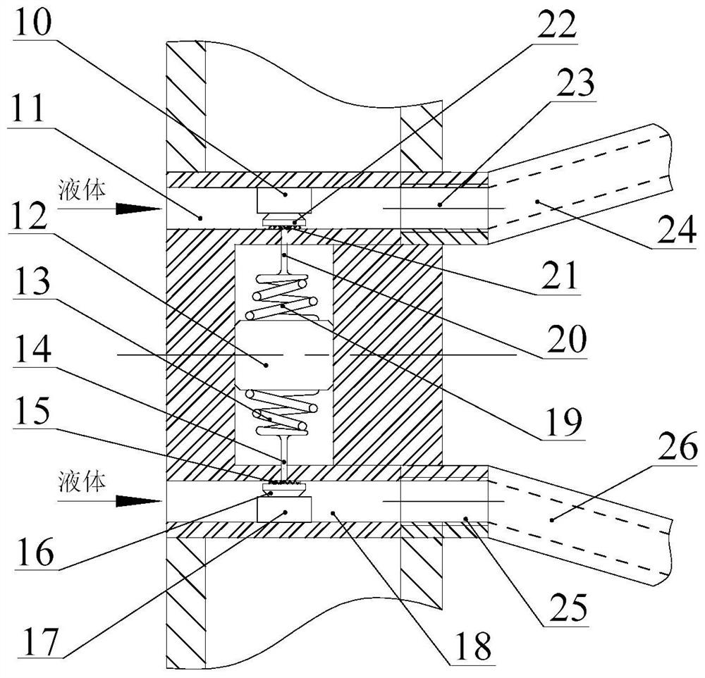
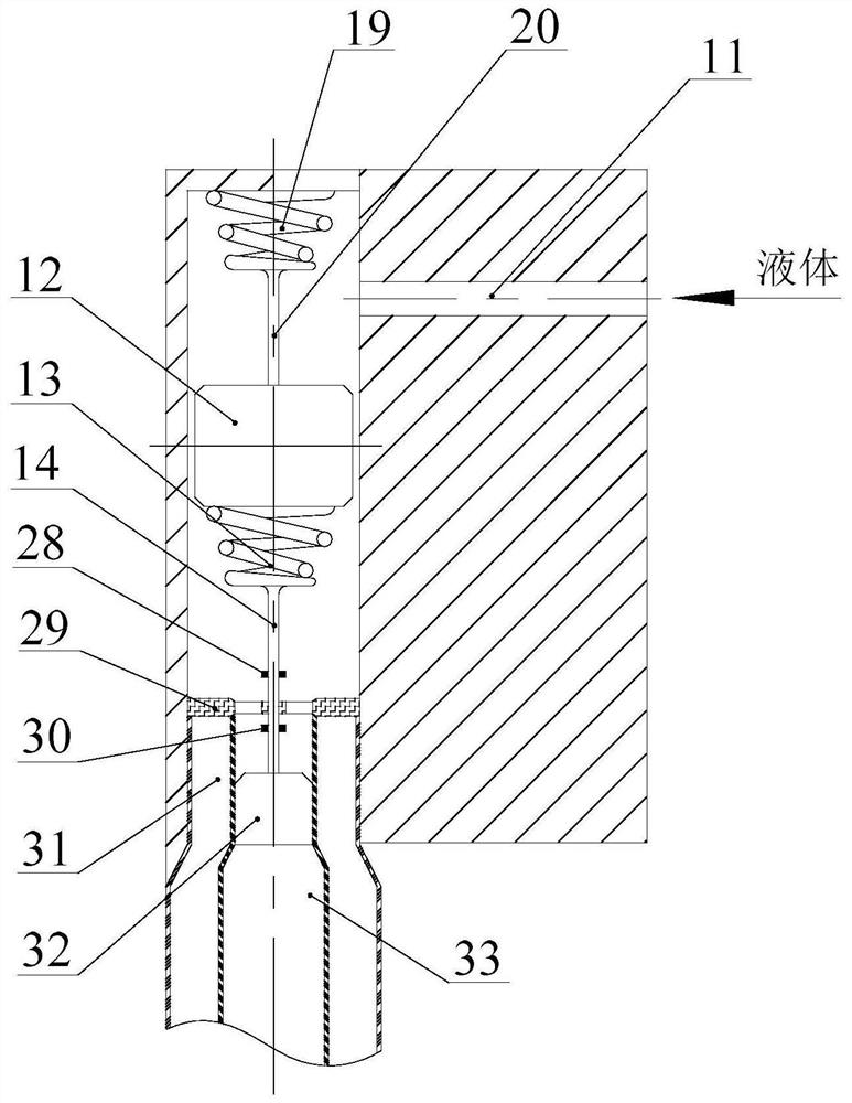
[0029] like figure 1 As shown, the acceleration control passive device of the present invention includes a cylinder 7, a upper lifting ear 1, and a lower lifting ear 9, and the upper lug 1 is connected to the piston 6, and the piston 6 is placed in the cylinder 7. The piston 6 divides the inner cavity of the cylinder 7 into an upper cavity and a lower chamber, and the piston rod 2 and the cylinder 7 achieve the seal, the upper cavity and the lower cavity of the upper hole 4, the upper cavity and the lower cavity 7 between the piston rod 2 and the cylinder 7. The through hole 4 of the cavity is connected by the main spiral tube 5 such that the liquid in the upper cavity and the lower chamber can achieve liquid flow through the main spiral tube 5. The inner wall of the cylinder 7 is equipped with a crash block 8 to prevent...


PUM


Abstract

The invention provides a device for passively realizing acceleration control, which includes a cylinder body, a piston and a main spiral tube. The piston divides the inner chamber of the cylinder body into an upper chamber and a lower chamber, and the upper chamber and the lower chamber are respectively connected Three helical tubes that generate different inertial forces, any two of the helical tubes communicate with the upper chamber or the lower chamber through a dynamic inertia valve, and the dynamic inertia valve selectively makes the two helical tubes Any of the helical tubes communicates with the upper or lower chamber. The invention can realize simple and semi-active passive control, and solves the difficulty in realizing current acceleration control.

Description

Technical field [0001] The present invention relates to the field of automobiles, and more particularly to an acceleration control passive implementation device. Background technique [0002] With the development of my country's transportation industry, the domestic passenger car is developed towards intelligent, high speed, light quantization and cleaning direction, and the requirements for vehicle energy saving are increasing. With the consolidation of the vehicle suspension structure, the improvement of the comprehensive performance of the normal passive suspension is increasingly approaching the limit, and the researchers gradually turn the semi-active control suspension and actively control the suspension. However, regardless of the half-active control suspension or actively controlling the suspension, it requires energy input other than the suspension, and the active suspension is slow to develop slowly because of high energy consumption. [0003] The development of the sma...

Claims


Application Information

Patent Timeline
Patent Type & Authority Patents(China)
IPC IPC(8): F16F9/18F16F9/19F16F9/32F16F9/34B60G17/08
CPCF16F9/18F16F9/19F16F9/3207F16F9/34B60G17/08F16F7/1034
Inventor 刘昌宁陈龙杨艺杨晓峰张孝良
Owner JIANGSU UNIV
Learn More