Processing equipment for anti-deformation wooden door and processing method thereof
A technology of processing equipment and processing methods, applied in wood processing equipment, manufacturing tools, etc., can solve the problems of easy deformation of wooden doors, unfavorable quietness, cumbersome operation, etc., and achieve the effects of convenient and fast installation, extended service life, and accurate processing dimensions
- Summary
- Abstract
- Description
- Claims
- Application Information
AI Technical Summary
Problems solved by technology
Method used
Image
Examples
Embodiment 1
[0034] A processing method for an anti-deformation wooden door, comprising the following steps:
[0035] A. Material preparation: According to the actual size requirements of customers, combined with Figure 7 Shown, prepare sealing plate, two door panels 28 and a plurality of wooden strips 29, the length of wooden strips 29 is all less than the length of door panel 28;
[0036] B, filler: apply glue on the opposite sides of two door panels 28, then stick the wooden strip 29 on the side surfaces of the door panels 28, specifically in conjunction with the present embodiment, in Figure 7 Glue is applied on the upper side of the middle and lower door panel 28 and the lower side of the upper door panel 28, and a plurality of wooden strips 29 are bonded on the upper side of the lower door panel 28 along the length direction of the door panel 28, and then the upper door panel 28 Buckled on the door panel 28 below, the door panel 28 above is bonded on the wooden strip 29, thus thro...
Embodiment 2
[0048] to combine Figure 3-Figure 4 As shown, the difference between this embodiment and Embodiment 1 is that in this embodiment, the fixed shaft 4 is in a stationary state, and the wooden door fixing frame is in a rotating state. Specifically, the left end of the fixed shaft 4 is welded to the shaft plate 3, the support disc 2 is provided with an annular cavity, the support disc 2 is divided into the middle part and the edge portion 22 by the annular cavity, and the rotary ring 19 is connected with the rotation in the annular cavity, and the left end of the wooden door holder is welded on the rotary ring 19. In order to realize fixing the edge portion 22 and the middle portion, the frame 1 is welded on the middle portion of the support plate 2, the frame 1 is welded with a connecting rod 21, and the end of the connecting rod 21 away from the frame 1 is welded to the left end of the edge portion 22 face. In this embodiment, a third motor 20 is provided below the frame 1 , an...
Embodiment 3
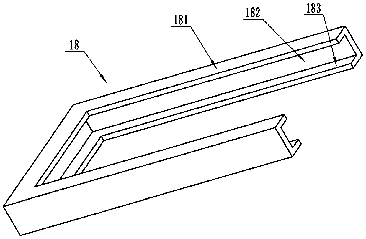
[0054] combine Figure 6 As shown, the difference between this embodiment and Embodiment 1 is that in this embodiment, the upper fixing part 181 is vertically slidably connected to the side of the fixing frame 18, and a vertical groove 187 is provided on the inner wall of the specific side. A slider is welded on the upper fixing part 181, and the slider is located in the vertical groove. The lower fixing part 183 is provided with a through hole, and the upper fixing part 181 is welded with a push rod 184. The bottom end of the push rod 184 passes through the through hole on the lower fixing part 183, and the bottom end of the push rod 184 is fixed with a first Magnets, on the top of the drive case 23 are fixed with a second magnet 186 by screws, and the magnetism of the sides facing each other between the second magnet 186 and the first magnet is the same. A tension spring 185 is connected between the upper fixing part 181 and the lower fixing part 183 , and the tension sprin...
PUM
 Abstract
Description
Claims
Application Information
 - Generate Ideas
- Intellectual Property
- Life Sciences
- Materials
- Tech Scout
- Unparalleled Data Quality
- Higher Quality Content
- 60% Fewer Hallucinations
Browse by: Latest US Patents, China's latest patents, Technical Efficacy Thesaurus, Application Domain, Technology Topic, Popular Technical Reports.
© 2025 PatSnap. All rights reserved.Legal|Privacy policy|Modern Slavery Act Transparency Statement|Sitemap|About US| Contact US: help@patsnap.com


