Desktop support capable of being assembled quickly

A desktop bracket and fast technology, applied in the field of intelligent lifting table, can solve the problems of cumbersome installation method, reduce production efficiency, increase production cost, etc., and achieve the effect of eliminating welding process, high production efficiency, and reliable use.

Pending Publication Date: 2020-07-24
CHANGZHOU KAIDI ELECTRICAL INC
View PDF0 Cites 5 Cited by
  • Summary
  • Abstract
  • Description
  • Claims
  • Application Information

AI Technical Summary

Problems solved by technology

However, the installation methods of existing desktop brackets on the market are generally cumbersome, see attached figure 1 And attached figure 2 , the longitudinal beam assembly 1 is provided with a slot 2, the slot 2 is provided with a mounting hole 201, the beam 3 is provided with a through hole 301 and a threaded hole 302 corresponding to the position of the mounting hole 201, and the beam 3 is set in the slot 2 Use the rubber bushing 4 to pass through the through hole 301 and the slot 2 in order to realize the positioning of the through hole 301 and the slot 2, and then use the hexagon socket head cap screw 5 to pass through the rubber bushing 4 and connect with the threaded hole 302 threaded assembly
[0003] The installation method of the above desktop bracket is to use the hexagon socket head cap screw 5 to lock and press the slot 2 in the stringer assembly 1, but the slot 2 needs to be welded on the stringer assembly 1, which increases the manufacturing cost and reduces the Improve production efficiency; at the same time, the screws need to be locked during assembly, and the assembly efficiency is low

Method used


Image

  • Desktop support capable of being assembled quickly
  • Desktop support capable of being assembled quickly
  • Desktop support capable of being assembled quickly

Examples


Embodiment 1

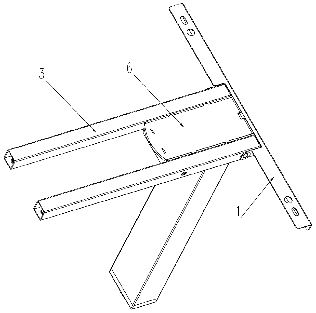
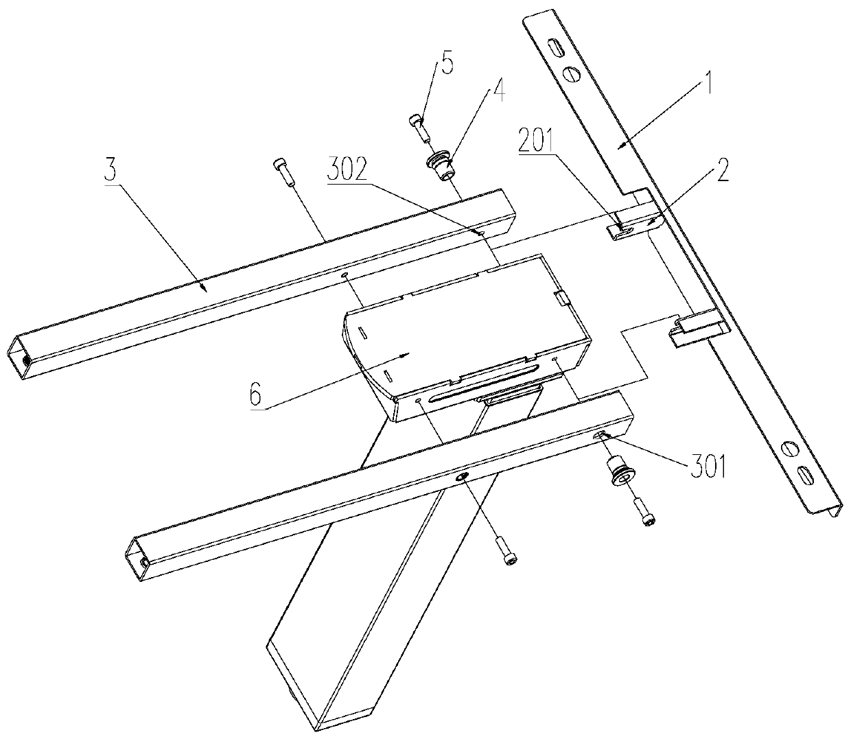
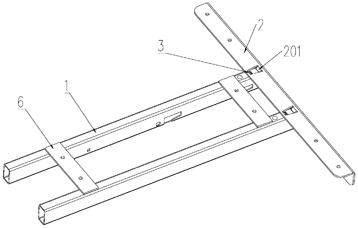
[0036] See Figure 3-7 , a rapidly assembled desktop support of the present invention can be matched with corresponding desktop boards to form a dining table, desk, office desk, conference table, student desk or coffee table, etc., with a beam 1 and a longitudinal beam 2 perpendicular to the beam 1.

[0037] A locking mechanism 3 is fixed on the crossbeam 1 , and the locking mechanism 3 is a leaf spring. The crossbeam 1 is provided with a first through hole 101 for the locking mechanism 3 to pop out. The locking mechanism 3 is made of spring steel. The locking mechanism 3 is composed of a connecting section 301 and a hemming section 302. The connecting section 301 and the hemming section 302 are integrally structured. The locking mechanism 3 is connected to the beam 1 through its connecting section 301 , the hemming section 302 has a pop-up part, the pop-up part includes a peak part 3022 and a guide part 3021 connected end to end, and the pop-up part pops out from the first th...

Embodiment 2

[0049] See Figure 8 , compared with Embodiment 1, the difference of Embodiment 2 is that the locking mechanism 3 and the crossbeam 1 are integrally structured, and the locking mechanism 3 is a part processed by the crossbeam 1. Specifically, the locking mechanism 3 utilizes the crossbeam 1 Stamping itself.

Embodiment 3

[0051] See Figure 9-10 , compared with embodiment 1, the difference of embodiment 3 is: the number of cross beams 1 is two groups, two groups of cross beams 1 are arranged along the length direction of the desktop bracket and distributed symmetrically left and right, and the inner cavities of two groups of cross beams 1 are interspersed There are connecting rods 4, and the number of connecting rods 4 is two. After the distance between the two groups of beams 1 is adjusted, they are respectively fixed with the corresponding ends of the connecting rods 4, so as to realize the adjustable length of the desktop support.


PUM


Abstract

The invention discloses a desktop support capable of being assembled quickly. The desktop support is provided with transverse beams and a longitudinal beam perpendicular to the transverse beams, and locking mechanisms are fixed to the transverse beams. The longitudinal beam is provided with steps and clamping groove corresponding to the steps in position. The longitudinal beam and the transverse beams are pushed to move relatively, so that the longitudinal beam and the steps of the longitudinal beam are in close fit with pipe walls of the transverse beams, the locking mechanisms are clamped into clamping grooves in the longitudinal beam, and rapid clamping of the transverse beams is achieved. The desktop support capable of being assembled quickly is high in production efficiency, simple instructure, convenient to install, reliable in use and adjustable in length.

Description

technical field [0001] The invention relates to the technical field of intelligent lifting tables, in particular to a rapidly assembled desktop bracket. Background technique [0002] As we all know, in daily life, the table plays a very important role, and people use it all the time. However, the installation methods of existing desktop brackets on the market are generally cumbersome, see attached figure 1 And attached figure 2 , the longitudinal beam assembly 1 is provided with a slot 2, the slot 2 is provided with a mounting hole 201, the beam 3 is provided with a through hole 301 and a threaded hole 302 corresponding to the position of the mounting hole 201, and the beam 3 is set in the slot 2 Use the rubber bushing 4 to pass through the through hole 301 and the slot 2 in order to realize the positioning of the through hole 301 and the slot 2, and then use the hexagon socket head cap screw 5 to pass through the rubber bushing 4 and connect with the threaded hole 302 T...

Claims


Application Information

Patent Timeline
Patent Type & Authority Applications(China)
IPC IPC(8): A47B13/00A47B9/00
CPCA47B13/003A47B9/00A47B2230/0037A47B13/06A47B2200/0012F16B12/38
Inventor 王健朱更兴
Owner CHANGZHOU KAIDI ELECTRICAL INC
Why Eureka
Try Eureka