Switch cabinet for arcing and pressure relief

A switchgear and arc burning technology, applied in the field of switchgear, can solve the problems that it is difficult to ensure the safety of on-site operators and objects, and achieve the effect of increasing cooling and filtering effects and ensuring safety

Pending Publication Date: 2020-07-17
XIAMEN HUADIAN SWITCHGEAR
View PDF0 Cites 0 Cited by
  • Summary
  • Abstract
  • Description
  • Claims
  • Application Information

AI Technical Summary

Problems solved by technology

[0006] The purpose of the present invention is to provide a switchgear for arcing and pressure relief to solve the problem that the pressure relief structure of the traditional switchgear is difficult to ensure the safety of on-site operators and objects during the internal arcing fault test

Method used


Image

  • Switch cabinet for arcing and pressure relief
  • Switch cabinet for arcing and pressure relief
  • Switch cabinet for arcing and pressure relief

Examples


Embodiment Construction

[0030] In order to make the object, technical solution and advantages of the present invention more clear, the present invention will be further described in detail below in conjunction with the accompanying drawings and embodiments. It should be understood that the specific embodiments described here are only used to explain the present invention, not to limit the present invention.

[0031] In describing the present invention, it should be understood that the terms "center", "longitudinal", "transverse", "length", "width", "thickness", "upper", "lower", "front", " Orientation indicated by rear, left, right, vertical, horizontal, top, bottom, inside, outside, clockwise, counterclockwise, etc. The positional relationship is based on the orientation or positional relationship shown in the drawings, which is only for the convenience of describing the present invention and simplifying the description, rather than indicating or implying that the referred device or element must hav...


PUM


Abstract

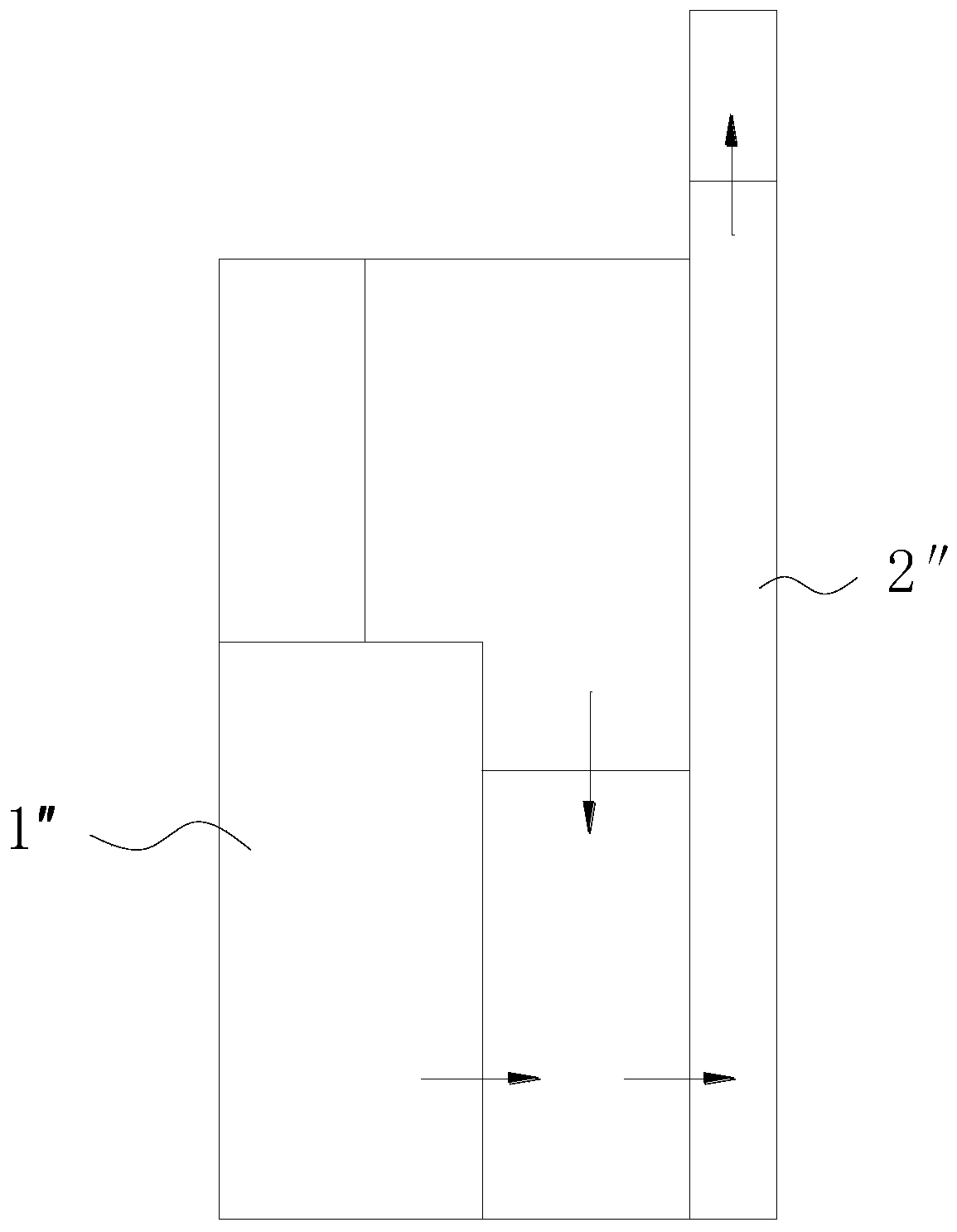
The invention relates to the technical field of switch cabinet main bodies, in particular to a switch cabinet for arcing and pressure relief. The switch cabinet comprises a pressure relief cabinet andat least one switch cabinet main body which are arranged side by side, a pressure relief chamber is arranged in the switch cabinet body, and a pressure relief opening communicated with the pressure relief chamber is formed at the lower portion of the side face of the switch cabinet body. The pressure relief cabinet comprises a cabinet body and a plurality of filtering assemblies, the lower part of the side surface of the cabinet body is provided with a connecting port, and the top is provided with a discharge port communicated with the external environment. The cabinet body is internally provided with a pressure relief channel bypassing the interior space of the cabinet body, the two ends of the pressure relief channel are respectively communicated with the connecting port and the discharge port, and the cabinet body is arranged at the side part of the switch cabinet main body. The connecting port is communicated with the pressure relief chamber, and the multiple filtering assembliesare arranged in the pressure relief channel at intervals. A melt conveyed from the pressure relief chamber is filtered out by the filtering assembly and is left in the cabinet body, so that the melt cannot be sprayed to the people and objects below the melt.

Description

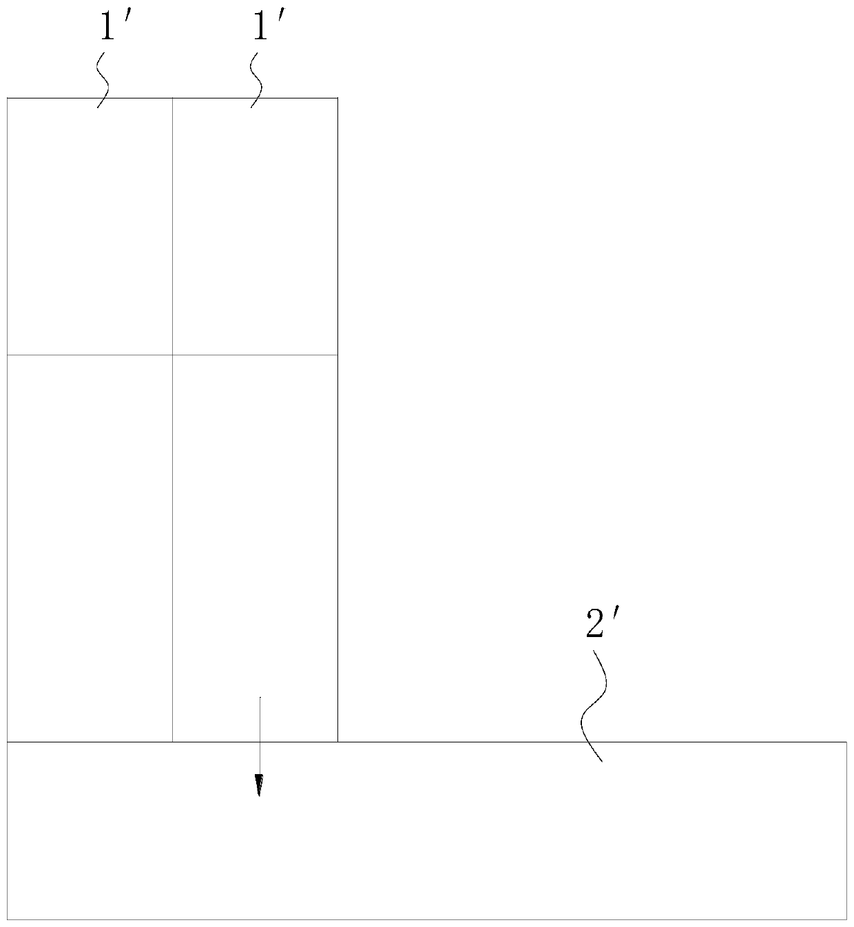
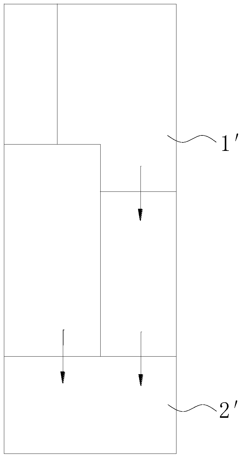
technical field [0001] The invention relates to the technical field of switch cabinets, in particular to a switch cabinet used for arcing and pressure relief. Background technique [0002] As a kind of electrical equipment, switchgear is mainly used for switching, controlling and protecting electrical equipment during the process of power generation, transmission, distribution and power conversion in the power system. Once the arcing fault such as internal short circuit occurs during the operation of the switchgear and the gas and burnt melt produced by the arcing fault cannot be discharged in time, it is easy to cause injury to the on-site operators and endanger the personal safety of the on-site operators. [0003] Such as figure 1 and figure 2 As shown in Fig. 1 , the measures for the common medium-voltage gas-insulated switchgear 1′ on the market to deal with the gas and burned melt produced by internal arcing faults are basically to introduce the gas and burned melt ...

Claims


Application Information

Patent Timeline
Patent Type & Authority Applications(China)
IPC IPC(8): H02B1/30H02B13/025
CPCH02B1/301H02B1/308H02B13/025
Inventor 李英联张兴朗郑闽生
Owner XIAMEN HUADIAN SWITCHGEAR
Why Eureka
Try Eureka