
Device for sleeving steel bars with pipes

A casing device and steel bar technology, applied in the field of building materials processing, can solve the problems of low efficiency of steel bar casing

Inactive Publication Date: 2020-07-17
SHANDONG BOCHUANG HEAVY IND CO LTD
View PDF1 Cites 0 Cited by
  • Summary
  • Abstract
  • Description
  • Claims
  • Application Information

AI Technical Summary

Problems solved by technology

[0007] In view of the above defects, the object of the present invention is to provide a steel casing device, aiming at solving the technical problem of low steel casing efficiency in the prior art

Method used


Image

  • Device for sleeving steel bars with pipes
  • Device for sleeving steel bars with pipes
  • Device for sleeving steel bars with pipes

Examples


Embodiment Construction

[0035] Below in conjunction with accompanying drawing, further elaborate the present invention.

[0036] The orientations involved in this specification are all based on the orientation of a reinforced casing device of the present invention when it is in normal operation, and are not limited to its orientation during storage and transportation, and only represent relative positional relationships, not absolute positional relationships.

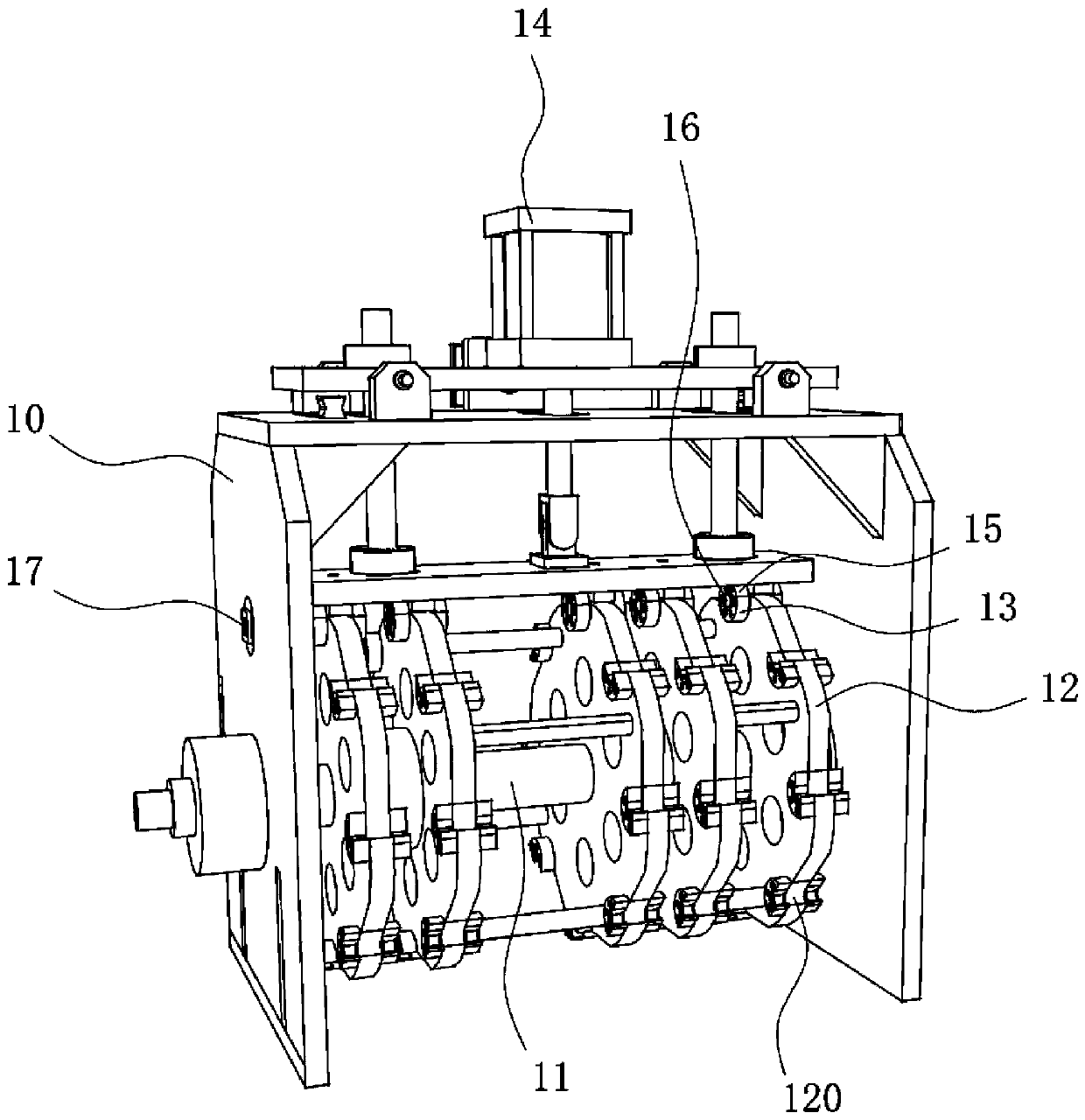
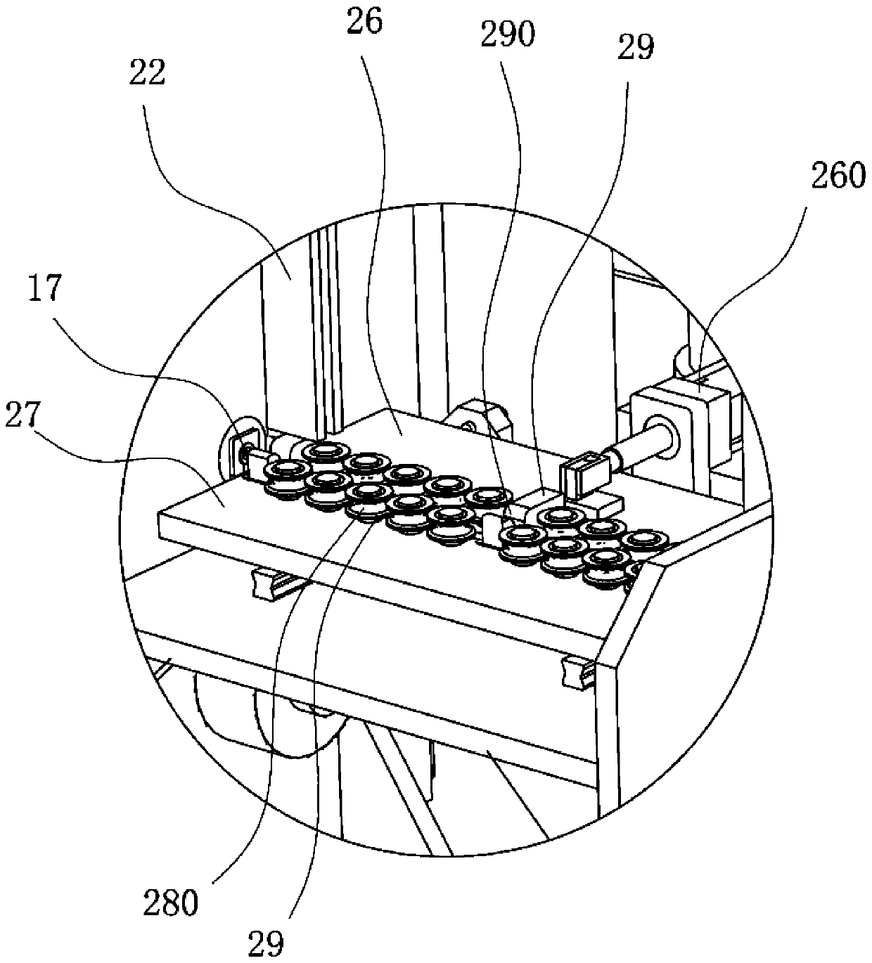
[0037] Such as Figures 1 to 5 Commonly shown, the steel bar casing device includes a casing mechanism 1, a steel bar feeding mechanism 2, a pipe section feeding mechanism 3, and a transfer mechanism. The steel bar feeding mechanism 2, the pipe section feeding mechanism 3, and the transfer mechanism are respectively connected to the casing mechanism 1 Above, the steel bar feeding mechanism 2 is used to continuously transport steel bars to the casing mechanism 1, and the pipe section feeding mechanism 3 is used to continuously deliver the pipe ...


PUM


Abstract

The device comprises a device for sleeving steel bars with pipes, and relates to the technical field of building material machining. The device comprises a pipe sleeving mechanism. The pipe sleeving mechanism comprises a first mounting rack. A first rotating shaft is rotationally mounted on the first mounting rack. Multiple rotating discs arranged in the axial direction of the first rotating shaftat intervals are coaxially and fixedly connected to the first rotating shaft. Multiple containing grooves used for containing pipe segments are arranged in the periphery of each rotating disc at intervals, and limiting blocks used for limiting the two ends of the corresponding pipe segments are mounted on the two sides of each rotating disc. A first linear drive mechanism located above the rotating discs is mounted on the first mounting rack. Press blocks are mounted at the action end of the first linear drive mechanism and are driven by the first linear drive mechanism to be pressed on the limiting blocks, and through holes capable of allowing steel bars to penetrate are formed in the pressing positions of the press blocks and the limiting blocks. According to the device for sleeving steel bars with pipes, the technical problem that the efficiency of sleeving steel bars with pipes is low in the prior art is solved. By means of the device, steel bars can be sleeved with pipes efficiently and accurately, the manufacturing cost is low, and automatic work can be achieved.

Description

technical field [0001] The invention relates to the technical field of building material processing, in particular to a steel bar casing device. Background technique [0002] The construction of high-speed railways or highways requires the use of a large number of steel reinforcement products, such as steel cages. The steel cages need to be covered with heat-shrinkable sleeves for insulation and protection. The existing production mode mainly relies on manual casing, and manual operation has the problems of low work efficiency and inaccurate positioning of steel bars and pipe sections. [0003] The Chinese patent with the application publication number CN107415216A discloses a fully automatic heat-shrinkable sleeve assembly line for high-speed railways. Specifically, the grippers installed on the retrieving truss are used to pick up the pipe section, and after being transferred to a specific position, pass The push block pushes the steel bar into the pipe section to realize...

Claims


Application Information

Patent Timeline
Patent Type & Authority Applications(China)
IPC IPC(8): B29C63/42B29C63/00
CPCB29C63/0004B29C63/42
Inventor 张志伟马春玉张志强黄明辉陈孝涛
Owner SHANDONG BOCHUANG HEAVY IND CO LTD
Learn More