
Stamping die for metal product casting

A technology for stamping dies and metal products, applied in the field of dies, can solve problems such as affecting the structural strength of the dies, deteriorating the working environment by noise, etc.

Inactive Publication Date: 2020-07-17
宋红龙
View PDF0 Cites 0 Cited by
  • Summary
  • Abstract
  • Description
  • Claims
  • Application Information

AI Technical Summary

Problems solved by technology

[0002] Mold is an important equipment for the mass production of metal products. Many of the metal parts are manufactured by stamping. During the stamping production process, high-frequency vibration is inevitable. Vibration will not only affect the strength of the mold structure, but also generate noise and deteriorate the work. Environment. With the development of stamping technology, the mold structure needs to be continuously improved to improve the quality in order to meet the needs of the mold industry. Based on the above premise, this case developed a stamping mold for metal product casting to solve this problem

Method used


Image

  • Stamping die for metal product casting
  • Stamping die for metal product casting
  • Stamping die for metal product casting

Examples


Embodiment 1

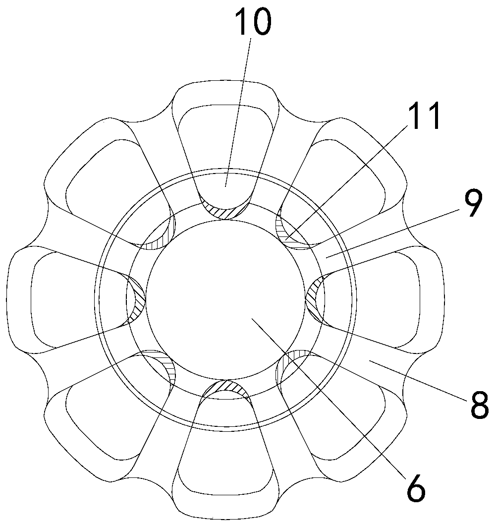
[0024] see figure 1 , the present invention provides a stamping die for metal product casting, its structure includes: upper die base 1, ejector punch 2, convex plate 3, spring plunger 4, said upper die base 1 is provided with ejector punch 2. The top position of the ejector punch 2 corresponds to the convex plate 3, the side of the convex plate 3 is connected to the spring plunger 4, and the upper mold base 1 is the main structure of the mold equipment. On the one hand, it plays the role of building the basic shape of the structure and carrying other The role of components, on the other hand, is used to protect the internal components in the process of stamping and manufacturing metal products. The ejector punch 2 is the core operating structure of the mold, and the convex plate 3 on the top is used The transformation of its displacement changes to shape the shape of the metal raw material to meet the production requirements. The spring plunger 4 is used to support the stabi...

Embodiment 2

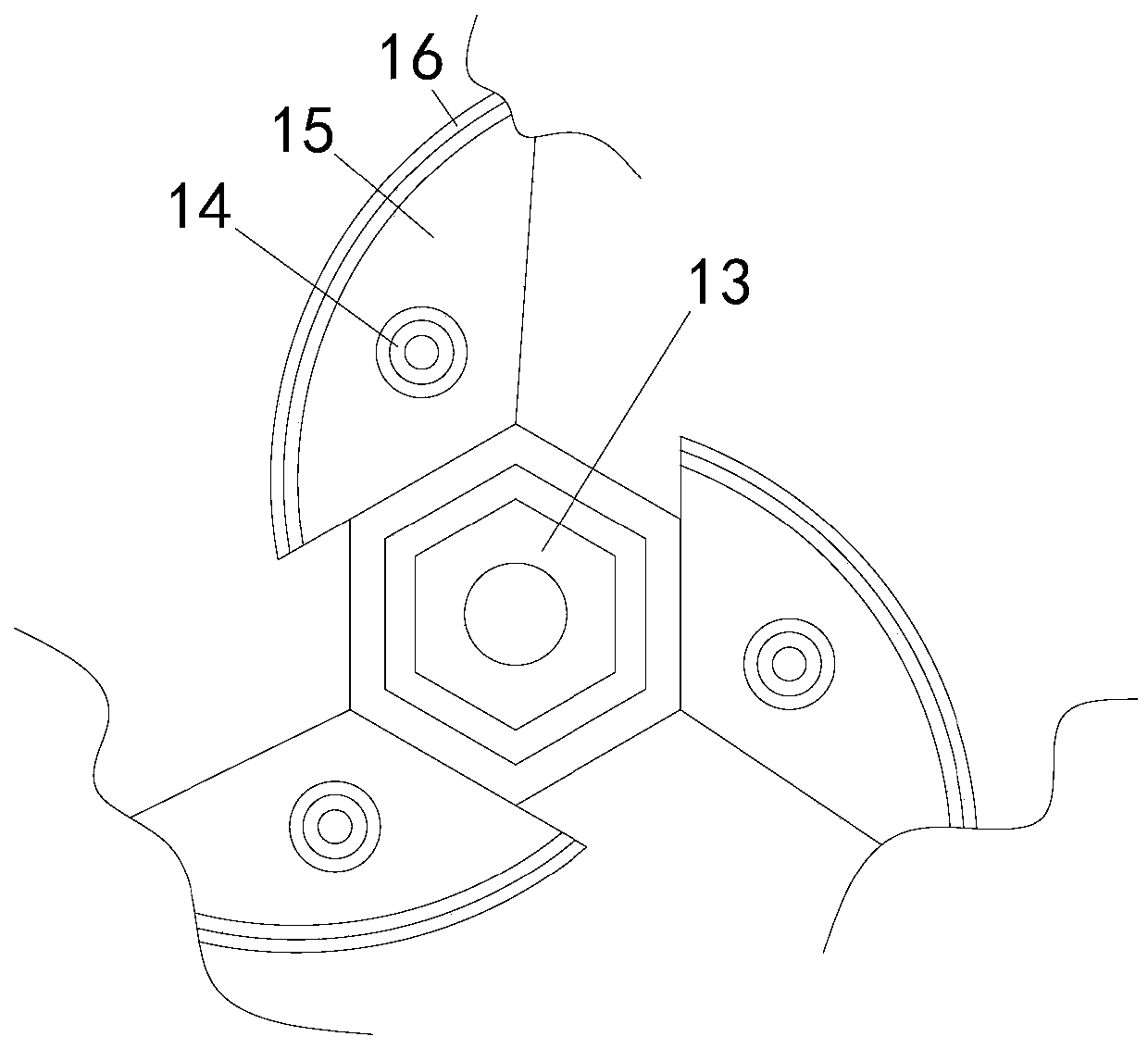
[0031] The description of the second embodiment drawn in conjunction with the first embodiment, combined with image 3 , Figure 4 and Figure 5 , the sides of the presser 13 are annularly equidistantly provided with isolation side pins 14, and the bottom of the rack 18 is provided with rebound layers 19 at intervals, and the rebound layers 19 and the sponge hole layer 20 are both arranged on the vertical block 21 of the machine tool , the vertical blocks 21 of the machine tool are connected by corrugated bars 22, and a stress wheel 26 is provided on one side of the spacer 25 and is connected to it. Magnetic rod 28, when the mold is stamping and manufacturing metal products, due to the different processing contents of each process, the pressure required for the press 13 to press the workpiece is also different, and the greater the pressure of the press 13, the greater the reaction force released , the reaction force acts on the presser 13, and the noise generated by the inst...


PUM


Abstract

The invention discloses a stamping die for metal product casting. The stamping die structurally comprises an upper die base, an ejection male die, a male die plate and a spring plunger, wherein the ejection male die is arranged in the upper die base, the male die plate is correspondingly arranged at the top of the ejection male die, and the side edge of the male die plate is connected with the spring plunger. The stamping die has the beneficial effects that sound waves generated by vibration are dispersed through a part pressing device arranged in the stamping die, a stable transmission stateof the sound waves in air is broken, resonance cannot be formed, meanwhile, the sound waves are absorbed and prevented from being continuously transmitted outwards, and resonance caused by the fact that the sound waves are transmitted to a structure is prevented, so that the influence of high-frequency vibration on the structural strength is avoided.

Description

technical field [0001] The invention relates to the field of molds, in particular to a stamping mold for casting metal products. Background technique [0002] Mold is an important equipment for the mass production of metal products. Many of the metal parts are manufactured by stamping. During the stamping production process, high-frequency vibration is inevitable. Vibration will not only affect the strength of the mold structure, but also generate noise and deteriorate the work. Environment, with the development of stamping technology, the mold structure needs to be continuously improved to improve the quality, so as to meet the needs of the progress of the mold industry. Based on the above premise, this case developed a stamping mold for metal product casting to solve this problem. Contents of the invention [0003] Aiming at the deficiencies of the prior art, the present invention is realized through the following technical solutions: a stamping die for casting metal pro...

Claims


Application Information

Patent Timeline
IPC IPC(8): B21D37/10B21D37/12F16F15/067F16F15/04G10K11/16G10K11/162
CPCB21D37/10B21D37/12F16F15/04F16F15/067G10K11/16G10K11/162G10K2210/129G10K2210/1291
Inventor 宋红龙
Owner 宋红龙
Learn More