
Land leveler and rear rack connecting structure of land leveler

A technology of connecting structure and rear frame, which is applied in the direction of earth mover/shovel, mechanically driven excavator/dredger, construction, etc., can solve the problem of low fatigue strength of the connecting structure of the rear frame, etc. Reliability, high flexural rigidity and strength, the effect of benefiting reliability

Inactive Publication Date: 2020-12-18
JIANGSU XCMG CONSTR MASCH RES INST LTD +1
View PDF4 Cites 0 Cited by
  • Summary
  • Abstract
  • Description
  • Claims
  • Application Information

AI Technical Summary

Problems solved by technology

[0005] Purpose: In order to overcome the deficiencies in the prior art, the present invention provides a motor grader and its rear frame connection structure, which solves the problem of the low fatigue strength of the current motor grader rear frame connection structure and the light weight of the motor grader rear frame connection structure question

Method used


Image

  • Land leveler and rear rack connecting structure of land leveler
  • Land leveler and rear rack connecting structure of land leveler
  • Land leveler and rear rack connecting structure of land leveler

Examples


Embodiment 1

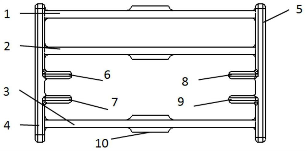
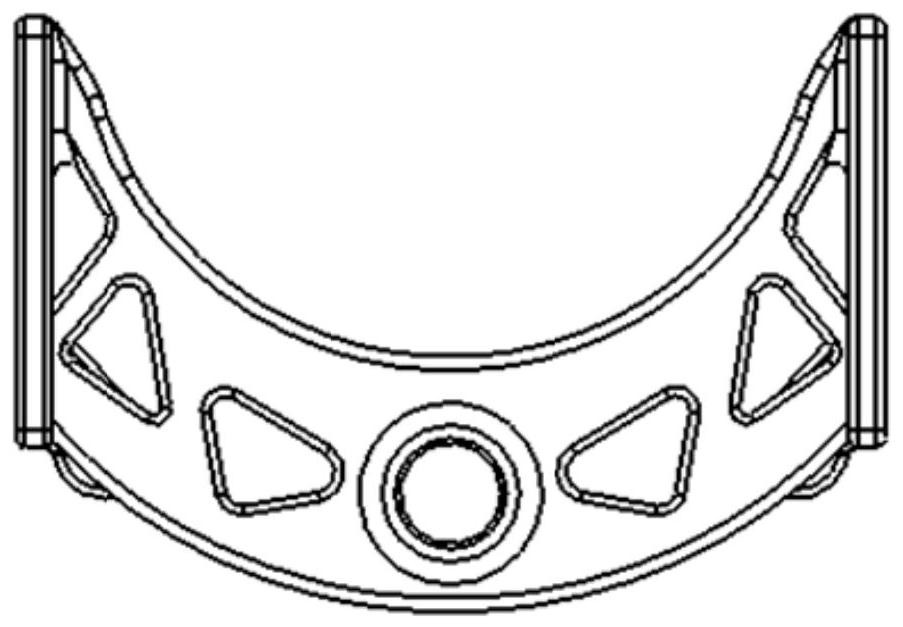
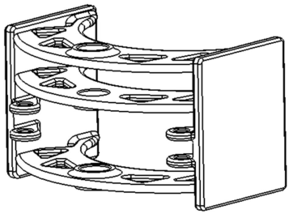
[0030] Such as Figure 1 to Figure 3 As shown, a rear frame connection structure of a grader includes a first upper hinged connection plate 1, a second upper hinged connection plate 2, a lower hinged connection plate 3, a left support plate 4, and a right support plate 5;

[0031] The left support plate 4 and the right support plate 5 are arranged vertically and parallel to each other;

[0032] The first upper hinged connecting plate 1, the second upper hinged connecting plate 2, and the lower hinged connecting plate 3 are arranged horizontally and parallel to each other from top to bottom; the first upper hinged connecting plate 1, the second upper hinged connecting plate One end of the hinged connecting plate 2 and the lower hinged connecting plate 3 is connected with the left support plate 4, and the other end is connected with the right support plate 5 to form a box structure; it is used to bear the bending resistance of the rear frame.

[0033] Corresponding positions on...

Embodiment 2

[0042] Such as Figure 5As shown, a grader includes the above-mentioned rear frame connection structure of the grader. Through the hinge pin holes 10 of the first upper hinged connecting plate 1, the second upper hinged connecting plate 2, and the lower hinged connecting plate 3, the hinge of the front frame 11 and the rear frame 12 is realized; further, turning One end of the oil cylinder is hinged with the hinge lugs on the inside of the left side support plate 4 and the right side support plate 5, and the telescopic drive of the steering oil cylinder drives the rear frame to realize turning.


PUM


Abstract

The invention discloses a land leveler and a rear rack connecting structure of the land leveler. The rear rack connecting structure of the land leveler comprises a first upper hinge connecting plate,a second upper hinge connecting plate, a lower hinge connecting plate, a left side supporting plate and a right side supporting plate; the left side supporting plate and the right side supporting plate are arranged in the vertical direction and are parallel; the first upper hinge connecting plate, the second upper hinge connecting plate and the lower hinge connecting plate are sequentially arranged in the horizontal direction from top to bottom; the two ends of the first upper hinge connecting plate, the second upper hinge connecting plate and the lower hinge connecting plate are connected with the left side supporting plate and the right side supporting plate correspondingly to form a box type structure; hinge pin holes are formed in the corresponding positions of the first upper hinge connecting plate, the second upper hinge connecting plate and the lower hinge connecting plate; lightening holes are formed in the first upper hinge connecting plate, the second upper hinge connecting plate and the lower hinge connecting plate correspondingly; and hinge lugs are further connected to the inner sides of the left side supporting plate and the right side supporting plate between the second upper hinge connecting plate and the second lower hinge connecting plate, and the hinge lugs are drop-shaped.

Description

technical field [0001] The invention belongs to the technical field of motor graders, and in particular relates to a motor grader and its rear frame connection structure. Background technique [0002] The grader is the main machine used for shaping and leveling operations in earthworks, and it is an important equipment in the construction of national defense projects, mine construction, road construction, water conservancy construction and farmland improvement. Since the engine of the motor grader is installed on the rear frame, and the operating device is installed on the front frame, the connection structure of the rear frame of the motor grader is a key component connecting the front frame and the rear frame, which not only bears the load transmission, but also needs to It has the function of front and rear rack rotation. The blade of the motor grader can move in 6 degrees of freedom in space, so the working conditions are complex and the postures are changeable. The re...

Claims


Application Information

Patent Timeline
Patent Type & Authority Applications(China)
IPC IPC(8): E02F9/08E02F3/80
CPCE02F9/0841E02F3/80
Inventor 侯鹏龙高乐段俊杰
Owner JIANGSU XCMG CONSTR MASCH RES INST LTD
Learn More