Waste gas treatment equipment
A technology for waste gas treatment equipment and exhaust cover, which is applied in the separation of dispersed particles, cleaning methods and utensils, chemical instruments and methods, etc.
- Summary
- Abstract
- Description
- Claims
- Application Information
AI Technical Summary
Problems solved by technology
Method used
Image
Examples
Embodiment 1
[0028] For example figure 1 -example Figure 6 Shown:
[0029] The invention provides a waste gas treatment device, the structure of which includes an exhaust cover 1, a liquid inlet 2, a purification pipe 3, a liquid discharge port 4, a base 5, and an air inlet 6, and the exhaust cover 1 is embedded in the purification pipe 3, the liquid inlet 2 is installed at the upper end of the side wall of the purification pipe 3, the liquid discharge port 4 is fixed at the lower end of the side wall of the purification pipe 3, the air inlet 6 and the purification pipe 3 The interior is connected, and the purification pipe 3 is welded to the base 5 .
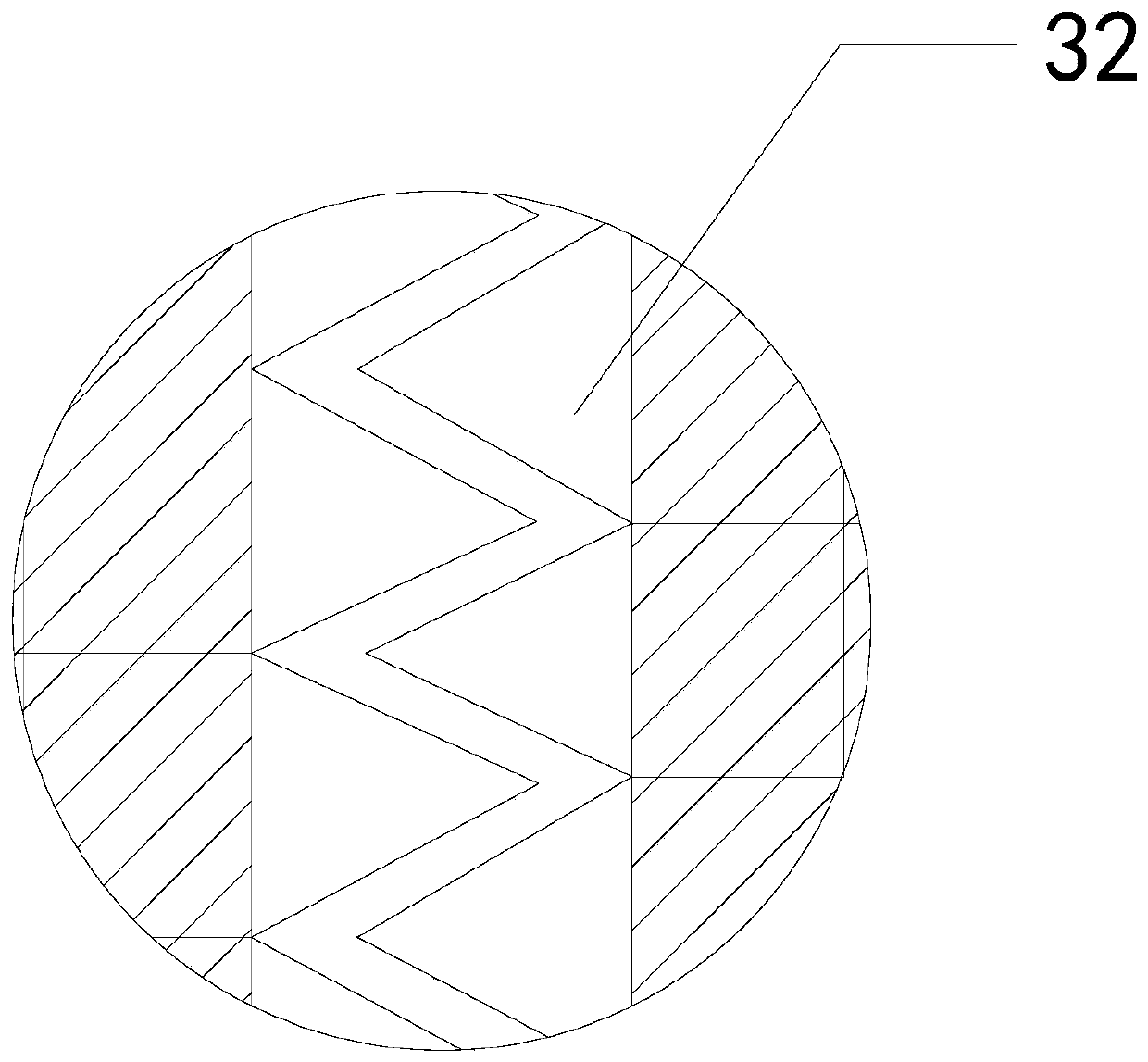
[0030] Wherein, the purification pipe 3 includes a spray head 31, a purification mechanism 32, a liquid redistributor 33, a liquid discharge tank 34, and an outer pipe 35, and the spray head 31 is embedded in the upper end of the inner wall of the outer pipe 35, so that The purification mechanism 32 is installed in the inner position of...
Embodiment 2
[0037] For example Figure 7 -example Figure 9 Shown:
[0038] Wherein, the liquid attachment plate a2 includes a linkage rod a21, a liquid receiving surface a22, a rotating ring a23, an extrusion plate a24, and a liquid absorption block a25, and one end of the linkage rod a21 is movably engaged with the upper end of the extrusion plate a24, In addition, the other end of the linkage rod a21 is connected to the liquid receiving surface a22, the extruding plate a24 is hingedly connected to the rotating ring a23, and the upper surface of the liquid absorbing block a25 is attached to the bottom surface of the liquid receiving surface a22. Both the liquid receiving surface a22 and the squeeze plate a24 are provided with liquid permeable holes, so that the liquid can pass through the inside, and the distance between the two liquid permeable holes on the squeeze plate a24 is relatively large, so that the The liquid generates a thrust on it, so that the extrusion plate a24 can swin...
PUM
 Abstract
Description
Claims
Application Information
 - Generate Ideas
- Intellectual Property
- Life Sciences
- Materials
- Tech Scout
- Unparalleled Data Quality
- Higher Quality Content
- 60% Fewer Hallucinations
Browse by: Latest US Patents, China's latest patents, Technical Efficacy Thesaurus, Application Domain, Technology Topic, Popular Technical Reports.
© 2025 PatSnap. All rights reserved.Legal|Privacy policy|Modern Slavery Act Transparency Statement|Sitemap|About US| Contact US: help@patsnap.com


