Method for determining gap between auxiliary shoulders of double-shoulder drill pipe joint

A drill pipe joint and determination method technology, applied in the direction of drill pipe, drill pipe, drilling equipment, etc., can solve the problems of oilfield economic loss, double shoulder drill pipe joint failure, and limit the performance of double shoulder drill pipe joint, etc., to achieve Significant technical progress and the effect of highlighting substantive features

Inactive Publication Date: 2020-07-14
SHANGHAI UNIV
View PDF4 Cites 1 Cited by
  • Summary
  • Abstract
  • Description
  • Claims
  • Application Information

AI Technical Summary

Problems solved by technology

Facing the increasingly harsh drilling operation environment of deep wells, ultra-deep wells and ultra-deep wells, double-shoulder drill pipe joint failure accidents still occur from time to time during field operations, causing huge economic losses to the oil field
The axial force borne by the drill string increases with the increase of the well depth, which limits the further development of the performance of the double-shoulder drill pipe joint
The auxiliary shoulder clearance has an important influence on the connection strength and sealing performance of the double-shoulder tool joint in use, but there is no method for determining the auxiliary shoulder clearance of the double-shoulder tool joint under different well depths and different axial forces. See the report

Method used


Image

  • Method for determining gap between auxiliary shoulders of double-shoulder drill pipe joint
  • Method for determining gap between auxiliary shoulders of double-shoulder drill pipe joint
  • Method for determining gap between auxiliary shoulders of double-shoulder drill pipe joint

Examples


Embodiment Construction

[0027] The present invention will be further described below in conjunction with the accompanying drawings and embodiments.

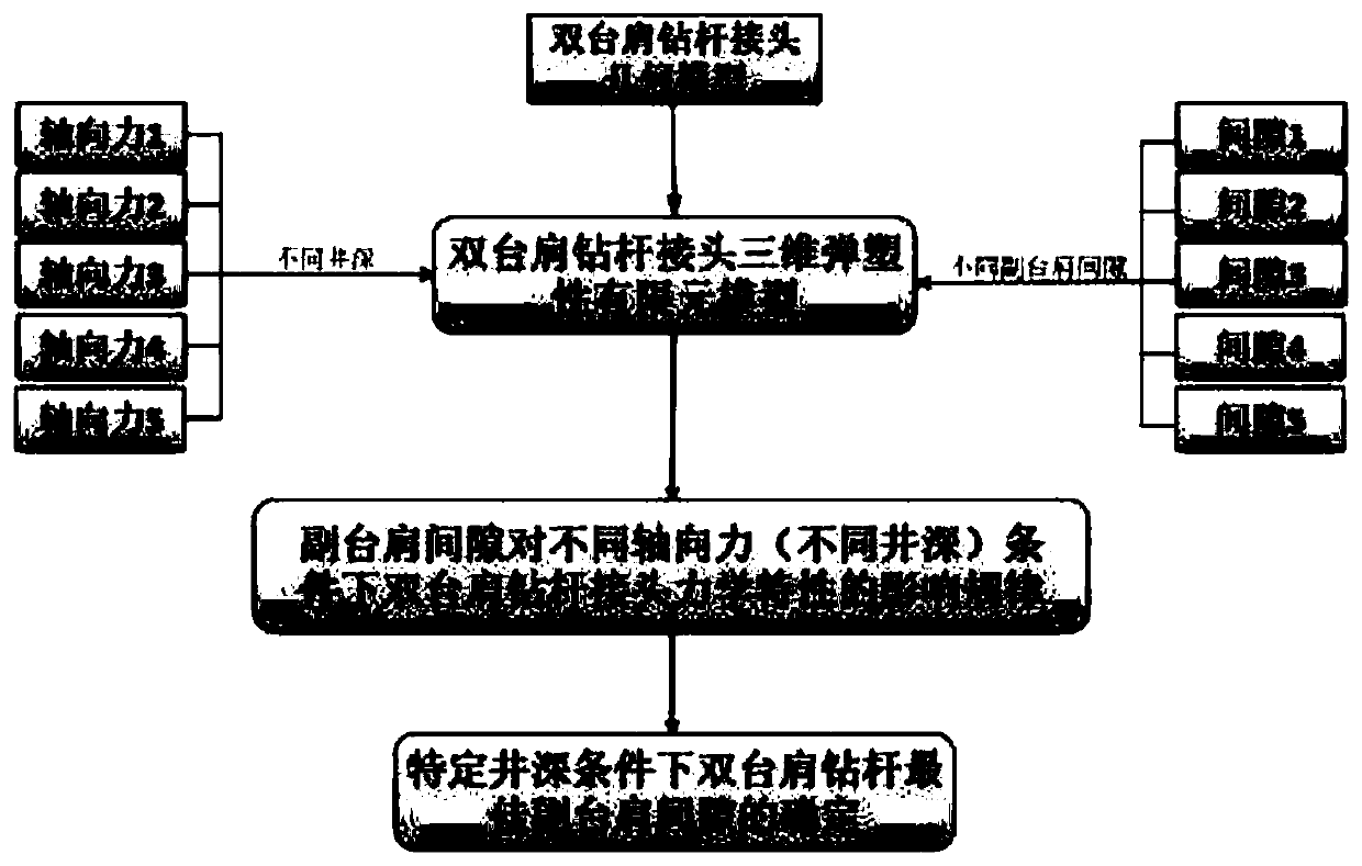
[0028] see figure 1 , a method for determining the secondary shoulder clearance of a double-shoulder drill pipe joint, according to the combined action of make-up torque, axial tension, bending moment, and working torque external loads of double-shoulder drill pipe joints with different secondary shoulder clearance characteristics Based on the stress characteristics of the three-dimensional elastoplastic finite element calculation, the optimal secondary shoulder clearance for this type of double-shoulder drill pipe joint suitable for a specific operating well depth is determined, including the following steps:

[0029] 1) Use special tools to measure the geometric parameters of the double-shoulder drill pipe joint, including joint outer diameter, inner diameter, thread tooth parameters, box bore, pin nose, shoulder parameters;

[0030] 2) Use the mater...


PUM


Abstract

The invention provides a method for determining a gap between auxiliary shoulders of a double-shoulder drill pipe joint. The method comprises the steps that a three-dimensional geometric model of thedouble-shoulder drill pipe joint is established according to the measured size data, and is subjected to grid division based on a multiblock grid method, and a three-dimensional elastoplastic finite element calculation model of the double shoulder drill pipe joint is established; on this basis, the three-dimensional force characteristics of double-shoulder drill pipe joints with different auxiliary shoulder gaps under the action of different axial forces are obtained based on the three-dimensional elastoplastic finite element analysis; and the gap between the auxiliary shoulders of the double-shoulder drill pipe joint which is most suitable for the axial force characteristics of a well section is preferably determined according to the depth characteristics of each section of a drill stem in ultra-deep well drilling operation. The method can determine the optimal gap between the auxiliary shoulders of the double-shoulder drill pipe joint so as to meet the requirements of different welldepth operations, and has very important significance on the improvement of the usability of the double-shoulder drill pipe joint, the prolonging of the service life of the double-shoulder drill pipejoint, and the reduction of the operation cost.

Description

technical field [0001] The invention relates to the technical field of oilfield drilling, in particular to a method for determining the secondary shoulder clearance of a double-shoulder drill pipe joint. Background technique [0002] With the development of oil and gas well drilling and production operations toward larger well depths and more severe service conditions and the technological progress of oil drilling and production technology itself, the commonly used API standard drill pipe joints have been difficult to meet the requirements of further development of oil and gas fields. Large drill pipe manufacturers have successively developed double-shoulder drill pipe joints with higher torsional performance. Since the double-shoulder drill pipe joint has better solved the problems of insufficient torsion resistance and serious stress concentration of the API standard drill pipe joint, its application range has been continuously expanded. [0003] The continuous reduction ...

Claims


Application Information

Patent Timeline
Patent Type & Authority Applications(China)
IPC IPC(8): E21B17/042E21B47/00G06F30/20
CPCE21B17/042E21B47/00
Inventor 陈锋狄勤丰王文昌朱巍靳雨果周星
Owner SHANGHAI UNIV
Why Eureka
Try Eureka