Reinforced concrete frame structure

A reinforced concrete and frame structure technology, applied in the direction of building components, building structures, building types, etc., can solve the problem of increasing the bending capacity of frame beams, and achieve the effect of improving seismic performance, good effect, and light weight

Active Publication Date: 2021-04-23
扬州市丰扬新特建材科技有限公司
View PDF8 Cites 0 Cited by
  • Summary
  • Abstract
  • Description
  • Claims
  • Application Information

AI Technical Summary

Problems solved by technology

[0003] The present invention intends to provide a reinforced concrete frame structure to solve the problem that the cast-in-place floor slab will increase the flexural bearing capacity of the frame beam

Method used


Image

  • Reinforced concrete frame structure
  • Reinforced concrete frame structure
  • Reinforced concrete frame structure

Examples


Embodiment Construction

[0020] The following is further described in detail through specific implementation methods:

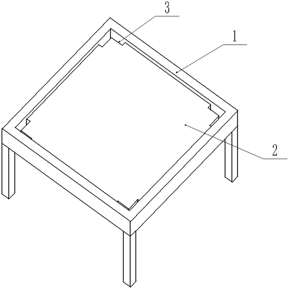
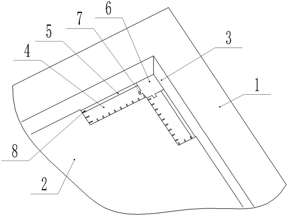
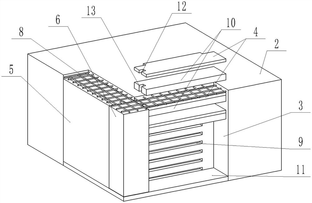
[0021] The reference signs in the drawings of the description include: frame beam 1, cast-in-place floor 2, partition groove 3, extruded board 4, second benzene board 5, post 6, block 7, steel wire 8, slot 9, the first A benzene board 10, a concrete layer 11, a first vertical through groove 12, and a second vertical through groove 13.

[0022] This example Figure 1-Figure 3 Shown:

[0023] Reinforced concrete frame structure, including cast-in-place floor slab 2 and frame beam 1. The four corners of the cast-in-place floor 2 and the end of the frame beam 1 are connected with an L-shaped partition groove 3, and the lengths of the two sides of the partition groove 3 are respectively equal to 1 / 8 of the span of the cast-in-place floor 2 in the corresponding direction. A filling structure is provided in the groove 3 .

[0024] The filling structure includes a concrete layer 11 , an ...


PUM


Abstract

The present invention relates to the technical field of building structures, and specifically discloses a reinforced concrete frame structure, including a cast-in-place floor slab and a frame beam, where four corners of the cast-in-place floor slab and the ends of the frame beam are connected with L-shaped partition grooves. The lengths of the two sides of the partition groove are respectively equal to 1 / 8 of the span of the cast-in-place floor in the corresponding direction, and the partition groove is provided with a filling structure, which includes a concrete layer, an extruded board, a first benzene board, a second benzene plate and post. The invention aims to solve the problem that the cast-in-place floor slab will increase the flexural bearing capacity of the frame beam.

Description

technical field [0001] The invention relates to the technical field of building structures, and specifically discloses a reinforced concrete frame structure. Background technique [0002] The seismic performance of reinforced concrete frame structures is closely related to the failure mechanism of the frame. The seismic design code proposes the seismic design principles of "strong columns and weak beams", "strong shear and weak bending", and "strong joints and weak members". method to achieve. However, actual earthquake damage and research have shown that the "column-hinge" failure mechanism of frame structures is relatively common, and an important reason for this phenomenon is that the contribution of cast-in-place slabs to the flexural capacity of frame beam ends has been ignored in the design. In fact, in the frame structure, the cast-in-place floor slab and the beam are co-cast, which participates in the stress of the beam, and improves the bending stiffness and bearin...

Claims


Application Information

Patent Timeline
Patent Type & Authority Patents(China)
IPC IPC(8): E04B1/00E04B5/28E04B1/20E04B1/21E04B1/98E04H9/02
CPCE04B1/00E04B1/20E04B1/21E04B1/98E04B5/28E04H9/021E04H9/025
Inventor 陈贞全
Owner 扬州市丰扬新特建材科技有限公司
Why Eureka
Try Eureka