
Slime sorting machine for collecting metal blocks

A metal block and sorting machine technology, which is applied in filtration separation, solid separation, magnetic separation, etc., can solve the problems that impurities are difficult to quickly clean up, and can not fully screen metal blocks, and achieve the effect of improving resource utilization.

Inactive Publication Date: 2020-07-14
陈先荣
View PDF12 Cites 2 Cited by
  • Summary
  • Abstract
  • Description
  • Claims
  • Application Information

AI Technical Summary

Problems solved by technology

[0005] In order to overcome the shortcomings that metal blocks of different sizes cannot be fully screened and impurities filtered by equipment are difficult to quickly clean up, the technical problem of the present invention is to provide a metal block that can fully screen metal blocks of different sizes and impurities filtered by equipment to facilitate rapid cleaning. Slime sorter for lump collection

Method used


Image

  • Slime sorting machine for collecting metal blocks
  • Slime sorting machine for collecting metal blocks
  • Slime sorting machine for collecting metal blocks

Examples


Embodiment 1

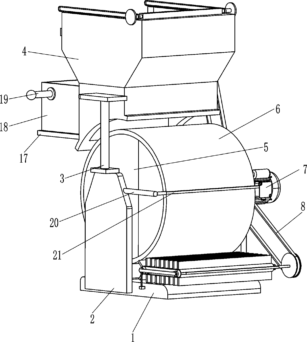
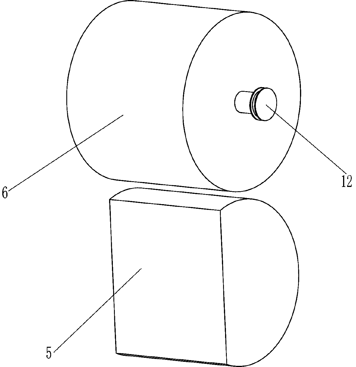
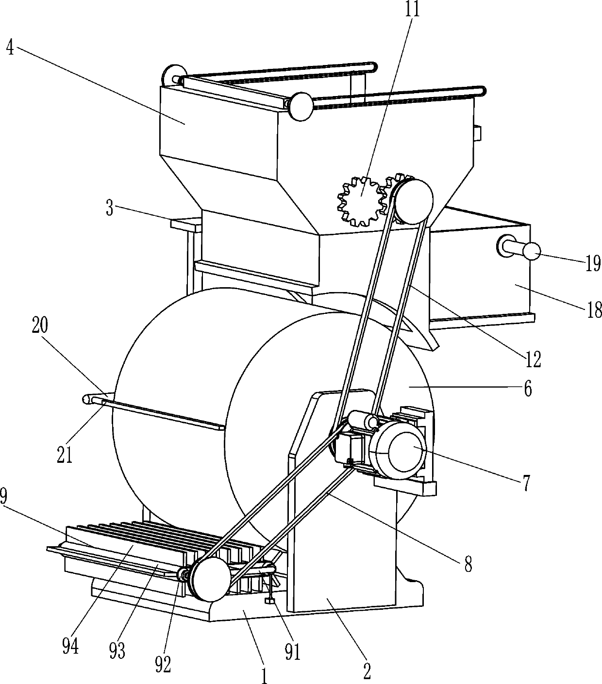
[0022] A slime separator for metal lump collection, such as Figure 1-4 As shown, it includes a bottom plate 1, a mounting plate 2, a mounting column 3, a filter frame 4, a magnetic column 5, a circular drum 6, a driving motor 7, a first transmission assembly 8, a pushing device 9, a squeeze roller 10, a driving Gear 11, second transmission assembly 12 and filter screen frame 13, base plate 1 front and rear sides are all provided with installation plate 2, front side installation plate 2 top is provided with installation column 3, is provided with filter frame 4 on installation column 3, front side The rear side of the mounting plate 2 is provided with a magnetic column 5, the rear mounting plate 2 is rotatably connected with a circular drum 6, the magnetic column 5 is attached to the inner wall of the circular drum 6, and the rear mounting plate 2 is provided with a drive motor 7 , the output shaft of the driving motor 7 is connected with the first transmission assembly 8, th...

Embodiment 2

[0026] On the basis of Example 1, such as image 3 As shown, guide rail 14, push handle 15, push plate 16, sliding plate 17, material receiving frame 18 and handle 19 are also included. Handle 15, push plate 16 is provided at the inner end of push handle 15 on both sides, the bottom of push plate 16 is in contact with the top of filter screen frame 13, a sliding plate 17 is provided on one side of filter frame 4, and the top of sliding plate 17 is slidingly provided with a receiving box 18. Both sides of the receiving frame 18 are provided with handles 19.

[0027] When the equipment is running, if a large amount of impurities are filtered on the top of the filter screen frame 13 and the mud continues to fall down, the worker can drive the push plate 16 to move to the left through the push handle 15, thereby pushing the impurities on the top of the filter screen frame 13. into the material receiving frame 18, while the push plate 16 can rotate freely to ensure that the push p...


PUM


Abstract

The invention relates to a slime sorting machine, in particular to a slime sorting machine for collecting metal blocks. The technical problem is how to provide the slime sorting machine for metal block collection, so that metal blocks in different sizes can be fully screened, and impurities filtered by equipment can be conveniently and rapidly cleaned. The slime sorting machine comprises a bottomplate, mounting plates, mounting columns, filter frames and the like. The mounting plates are arranged on the front side and the rear side of the bottom plate, the mounting columns are arranged at thetops of the front the mounting plates, and the filtering frames are arranged on the mounting columns. Through the cooperation of the magnetic columns and the devices on the magnetic columns, metal blocks in different sizes mixed in slime can be efficiently and rapidly screened out, compared with a traditional screening mode, the metal blocks with small sizes are not prone to being omitted, and the resource utilization rate is increased.

Description

technical field [0001] The invention relates to an ore slime separator, in particular to an ore slime separator for metal block collection. Background technique [0002] In non-ferrous metal mines, due to various reasons, a large amount of metal substances are mixed into the slime, because there are metal pieces with different sizes in the slime. Sieve, so that the grid gaps of the mesh screen are relatively large, making it difficult for some metal blocks with small volumes to be screened out, resulting in a certain waste. [0003] According to a Chinese invention disclosed on June 9, 2017, a heavy metal screening machine for sand and soil, its publication number is CN104324799B, hereinafter collectively referred to as Invention A, the main technical problem solved by Invention A is how to extend the service life of equipment with long working hours , without actually considering the screening capabilities of the equipment. [0004] Therefore, it is necessary to design a ...

Claims


Application Information

Patent Timeline
IPC IPC(8): B03C1/30B03C1/10B02C4/08B08B1/02B01D29/03B01D29/64
CPCB03C1/30B03C1/10B02C4/08B01D29/03B01D29/6484B01D2029/033B08B1/165B08B1/20
Inventor 陈先荣
Owner 陈先荣
Learn More