
High-voltage self-centering blind-mating floating connector and assembling method thereof

A floating connector and self-centering technology, which is applied to the assembly/disassembly of two-part connection devices, parts of connection devices, and contacts, etc., can solve the problem of limited pressure resistance range, damage to connectors and cables, and fatigue resistance Insufficient reliability and other issues, to achieve the effect of extending the creepage distance and improving the withstand voltage level

Pending Publication Date: 2020-07-10
成都合众宝根电子有限公司
View PDF0 Cites 3 Cited by
  • Summary
  • Abstract
  • Description
  • Claims
  • Application Information

AI Technical Summary

Problems solved by technology

[0004] 1. The floating part is a bellows and other similar structures. The axial expansion and contraction of the connector and the radial swing are realized through the elasticity of the bellows. This mechanism determines its fatigue resistance and reliability due to the structure of the bellows itself. Insufficient, permanent deformation is prone to occur after use, and manual correction is required, otherwise the set of connectors will fail and be scrapped, and the radial and axial swing / floating ranges are not easy to control;
[0005] 2. Limited by the size and structure, the range of pressure resistance is limited, and in order to make the pressure resistance meet the standard, multi-layer sealing rings are used for sealing, which leads to problems such as excessive insertion and withdrawal force of the connector and low pressure resistance range;
[0006] 3. The lead-out cable lacks a proper fixing mechanism, and there is a risk of damage to the connector and the cable during the swing of the cable

Method used


Image

  • High-voltage self-centering blind-mating floating connector and assembling method thereof
  • High-voltage self-centering blind-mating floating connector and assembling method thereof
  • High-voltage self-centering blind-mating floating connector and assembling method thereof

Examples


Embodiment Construction

[0031] The specific embodiments of the present invention are described below so that those skilled in the art can understand the present invention, but it should be clear that the present invention is not limited to the scope of the specific embodiments. For those of ordinary skill in the art, as long as various changes Within the spirit and scope of the present invention defined and determined by the appended claims, these changes are obvious, and all inventions and creations using the concept of the present invention are included in the protection list.

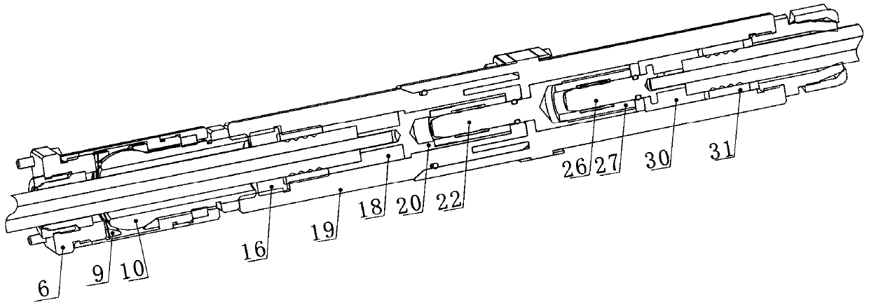
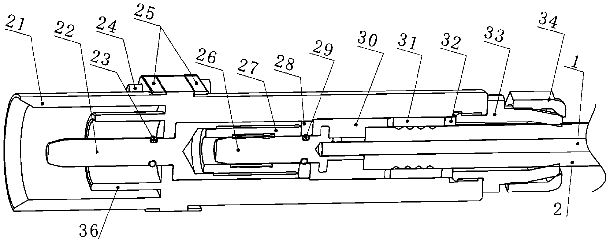
[0032] Such as Figure 1 to Figure 3 As shown, the high-voltage self-centering blind plug floating connector includes a plug and a socket. The plug includes a jack sleeve 20. One end of the jack sleeve 20 is provided with a first jack, and the other end is connected to the inner conductor 1 of the cable 2. Jack sleeve 20 is provided with a plug shell 19; one end of jack sleeve 20 connected to inner conductor 1 is insulated ...


PUM


Abstract

The invention discloses a high-voltage self-centering blind-mating floating connector which comprises a plug and a socket; the plug comprises a jack sleeve, one end, connected with an inner conductor,of the jack sleeve is in insulation connection with a hollow spherical column, an elastic ring is arranged at the ball head end of the spherical column, a fastener is arranged outside the spherical column, and the elastic ring is fixed in the fastener through a support; the socket comprises an adapter plug, one end of the adapter plug is inserted into a first jack, and the other end of the adapter plug is fixedly connected with the inner conductor of the cable. The spherical column in the plug can realize rotation, swing and transverse movement, the creepage distance in the plug and the socket is prolonged through a plastic package process, and the voltage withstanding level is greatly improved in a limited space. An assembling method of the connector comprises the steps of assembling theplug and the socket, realizing connection between the cable and the conductor through a plastic packaging process, realizing simple whole assembling process, and ensuring high-voltage conduction while ensuring firm sealing of the socket and the plug.

Description

technical field [0001] The invention relates to the technical field of connectors, in particular to a high-voltage self-centering blind-mating floating connector and an assembly method thereof. Background technique [0002] The high-voltage self-centering blind-mating floating connector is a connector that transmits instantaneous high-voltage and high-current. The conventional operation in use is to push up the pre-installed integral light box with the plug and match it with the prefabricated socket on the upper end. According to This enables transmission of current and voltage. [0003] Usually the main problems of high-voltage connectors are: [0004] 1. The floating part is a bellows and other similar structures. The axial expansion and contraction of the connector and the radial swing are realized through the elasticity of the bellows. This mechanism determines its fatigue resistance and reliability due to the structure of the bellows itself. Insufficient, permanent de...

Claims


Application Information

Patent Timeline
Patent Type & Authority Applications(China)
IPC IPC(8): H01R13/631H01R13/04H01R13/10H01R13/502H01R4/18H01R31/06H01R24/00H01R43/20
CPCH01R4/18H01R13/04H01R13/10H01R13/502H01R13/6315H01R24/005H01R31/06H01R43/20
Inventor 陈学军严良勇
Owner 成都合众宝根电子有限公司
Learn More