
Detachable pulse power capacitor and assembling method

A technology of pulse power and capacitors, which is applied in the field of detachable pulse power capacitors and assembly, can solve the problems of high price of pulse power capacitors, unusable capacitors, and increased customer costs, and achieve simple structure, improved reliability, and increased utilization. Effect

Pending Publication Date: 2020-07-10
FUJIAN TORCH ELECTRON TECH CO LTD
View PDF0 Cites 0 Cited by
  • Summary
  • Abstract
  • Description
  • Claims
  • Application Information

AI Technical Summary

Problems solved by technology

[0002] In the prior art, the pulse power capacitor fixes multiple chips together. During use, even if only one chip fails, the entire capacitor will be unusable, and the failed chip and the non-failed chip can only be scrapped together. However, the price of pulse power capacitors is high, which will cause serious waste and greatly increase the cost of customers

Method used


Image

  • Detachable pulse power capacitor and assembling method
  • Detachable pulse power capacitor and assembling method

Examples


Embodiment Construction

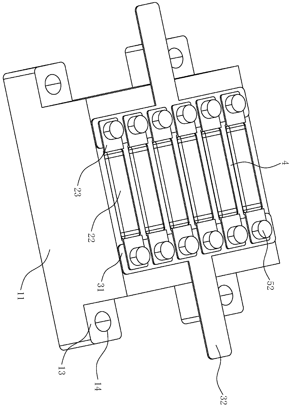
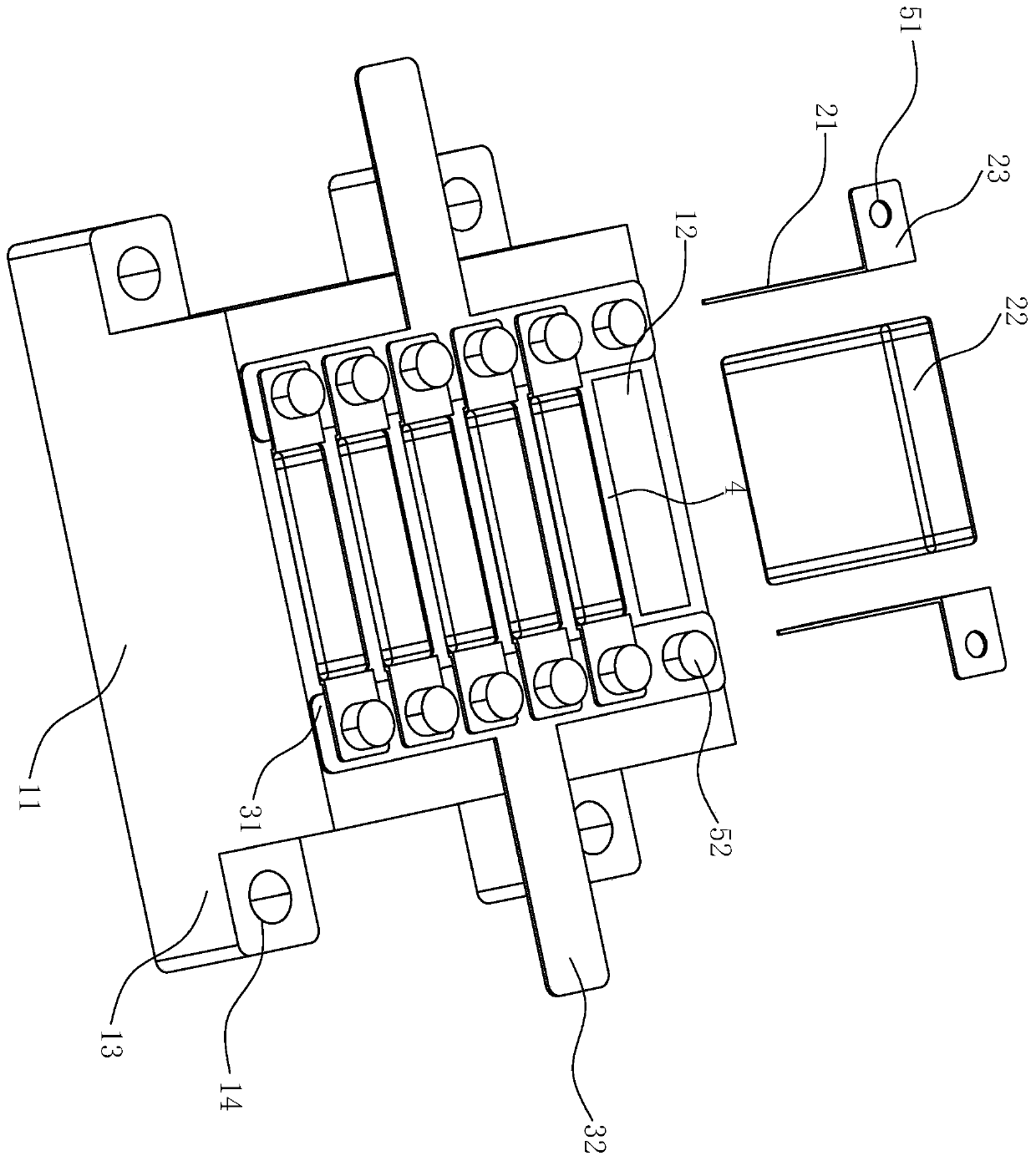
[0023] Such as figure 1 and figure 2 As shown, the detachable pulse power capacitor includes an insulating base, multiple capacitor welding groups, two lead frames and two fixing mechanisms. Multiple capacitor welding groups are detachably arranged on the base at intervals, and two adjacent capacitor welding groups are arranged between There is an isolation part 4, and two lead frames are relatively arranged on both sides of multiple capacitor welding groups. One lead frame is detachably connected to one end of multiple capacitor welding groups, and the other lead frame is detachably connected to the other end of multiple capacitor welding groups. .

[0024] The base includes a base 11 , a plurality of grooves 12 arranged at intervals on the upper surface of the base 11 , and a plurality of fixing seats 13 arranged outside the base 11 . The groove 12 is matched with the capacitor welding group for its insertion. The depth of the groove 12 is slightly smaller than the height...


PUM


Abstract

The invention provides a detachable pulse power capacitor. The capacitor comprises an insulating base, a plurality of capacitor welding groups and two lead frames, the plurality of capacitor welding groups are detachably arranged on the base at intervals; an isolation part is arranged between two adjacent capacitor welding groups, the two lead frames are oppositely arranged at two sides of the plurality of capacitor welding groups, one lead frame is respectively and detachably connected with one ends of the plurality of capacitor welding groups, and the other lead frame is respectively and detachably connected with the other ends of the plurality of capacitor welding groups. The invention further provides an assembling method of the detachable pulse power capacitor. The use reliability ofthe pulse power capacitor is improved, the failed capacitor welding set can be independently replaced, waste is avoided, the cost is saved, and the use rate of the pulse power capacitor is greatly improved.

Description

technical field [0001] The invention relates to a detachable pulse power capacitor and an assembly method. Background technique [0002] In the prior art, the pulse power capacitor fixes multiple chips together. During use, even if only one chip fails, the entire capacitor will be unusable, and the failed chip and the non-failed chip can only be scrapped together. However, the price of pulse power capacitors is high, which will cause serious waste and greatly increase the cost of customers. Contents of the invention [0003] The purpose of the present invention is to address the deficiencies of the prior art, and propose a detachable pulse power capacitor and an assembly method, which improves reliability, and can replace the failed capacitor welding group alone, avoiding waste, saving costs, and greatly improving pulse power Capacitor usage. [0004] The present invention is realized through the following technical solutions: [0005] A detachable pulse power capacitor...

Claims


Application Information

Patent Timeline
Patent Type & Authority Applications(China)
IPC IPC(8): H01G4/224H01G4/38H01G4/228
CPCH01G4/224H01G4/38H01G4/228
Inventor 朱江滨吴文辉吴育东吴明钊陈膺玺陈雅莹
Owner FUJIAN TORCH ELECTRON TECH CO LTD
Learn More