
Lens support, lens driving device, camera and electronic equipment

A technology of lens driving device and lens bracket, which is applied in the field of camera and electronic equipment, lens bracket, and lens driving device. It can solve the problems of uneven coil winding and untidy arrangement of lead wires, etc., and achieve the effect of neat coil winding

Pending Publication Date: 2020-07-10
NEW SHICOH MOTOR CO LTD
View PDF0 Cites 2 Cited by
  • Summary
  • Abstract
  • Description
  • Claims
  • Application Information

AI Technical Summary

Problems solved by technology

[0002] In the prior art, the existing lens holder has no lead groove, and the lead wires cannot be arranged neatly. Since the coil of the lens holder is not neatly wound, the height of the wound coil must be greater than that of the lens with the lead groove of this solution. Bracket, so it is necessary to add a lead groove to the lens holder, and the lead wire of the coil will have a transition, which can make the wiring neat

Method used


Image

  • Lens support, lens driving device, camera and electronic equipment
  • Lens support, lens driving device, camera and electronic equipment
  • Lens support, lens driving device, camera and electronic equipment

Examples


Embodiment 1

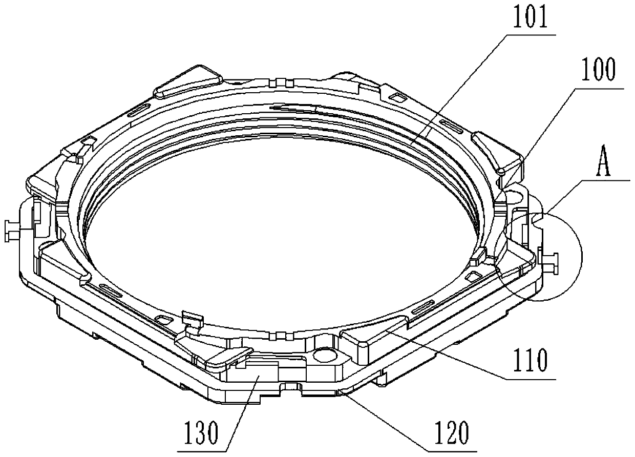
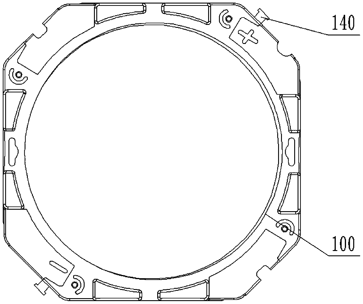
[0042] Example 1, please refer to Figure 1-6 , a lens holder, comprising a lens holder body 100,

[0043] The lens holder body 100 is flat and cylindrical, and the axis of the lens holder body 100 is provided with a circular lens mounting hole 101 for installing the lens 700. The extension of the lens holder body 100 is octagonal,

[0044] The upper and lower ends of the lens holder body 100 are respectively provided with an upper flange part 110 and a lower flange part 120, between the upper flange part 110 and the lower flange part 120 is a coil winding part 130, and the coil winding part 130 A coil is wound on it;

[0045] The extension of the lower flange part 120 is provided with a protruding part 140, which is used to fix the lead wire of the coil. on the edge of

[0046] The protruding portion 140 is in the shape of a rectangular column, and the end of the protruding portion 140 is provided with a rectangular blocking portion 141, the blocking portion 141 is used to...

Embodiment 2

[0051] Example 2, please refer to Figure 7-15 , a lens driving device, including a frame 300, a housing 400, a lower elastic piece 500 and an upper elastic piece 600; the housing 400 and the lower elastic piece 500 are installed on the frame 300, the frame 300 is approximately in the shape of a rectangular plate, and the frame The center card of 300 is provided with a through hole for light to pass through;

[0052] The housing 400 is approximately in the shape of a square box with an opening at the bottom. The top axis of the housing 400 is provided with a through hole for passing light, and the bottom opening of the housing 400 is fixedly buckled on the frame 300 on the outer edge of the

[0053] The four corners of the frame 300 are provided with guide pillars 301, and the outer sides of the guide pillars 301 are arranged in an arc-shaped transition, while the four corners of the inner wall of the housing 400 are also arranged in an arc-shaped transition. The four corners ...

Embodiment 3

[0062] Embodiment 3, a camera including the above-mentioned lens driving device.


PUM


Abstract

The invention discloses a lens support, a lens driving device, a camera and electronic equipment. The lens support comprises a lens support body, the upper end and the lower end of the lens support body are respectively provided with an upper flange part and a lower flange part, a coil winding part is arranged between the upper flange part and the lower flange part, and a coil is wound on the coilwinding part; a protruding part is arranged on the outer edge of the lower flange part, the protruding part is in a rectangular column shape, a rectangular blocking part is arranged at the tail end of the protruding part, the blocking part is used for preventing a lead wound on the protruding part from disengaging, and a lead groove is formed in the position, close to the protruding part, of thelower flange part. According to the lens support with the lead wire groove, the coil can be wound more orderly, the height of the coil winding part can be reduced on the premise that the lens supportwith the lead wire groove in the scheme obtains the same using effect, and the size of the whole lens driving device can be reduced.

Description

technical field [0001] The invention relates to the field of voice coil motors, in particular to a lens holder, a lens driving device, a camera and electronic equipment. Background technique [0002] In the prior art, the existing lens holder has no lead groove, and the lead wires cannot be arranged neatly. Since the coil of the lens holder is not neatly wound, the height of the wound coil must be greater than that of the lens with the lead groove of this solution. Bracket, so it is necessary to add a lead groove to the lens holder, and the lead wire of the coil will have a transition, which can make the wire arrangement neat. Contents of the invention [0003] The object of the present invention is to provide a lens holder, a lens driving device, a camera and an electronic device, so as to solve the problems raised in the background art above. [0004] To achieve the above object, the present invention provides the following technical solutions: [0005] A lens holder, ...

Claims


Application Information

Patent Timeline
Patent Type & Authority Applications(China)
IPC IPC(8): G02B7/02G03B13/36G03B5/00
CPCG02B7/02G03B5/00G03B13/36
Inventor 靖二勇
Owner NEW SHICOH MOTOR CO LTD
Learn More