
Constant speed woven belt winding machine

A technology of braided tape and tape winding machine, which is applied in the direction of winding strips, thin material processing, transportation and packaging, etc., and can solve the problems of affecting the effect of tape winding, failure to achieve automation, and low production efficiency.

Active Publication Date: 2016-09-28
沈传良
View PDF6 Cites 1 Cited by
  • Summary
  • Abstract
  • Description
  • Claims
  • Application Information

AI Technical Summary

Problems solved by technology

[0002] After the existing woven tape is woven in the weaving machine, it is usually directly transported to the collection basket, and then the worker connects one end of the messy woven tape to the foot-operated tape winding machine. This tape winding machine mainly includes a frame. A turntable is set in the middle of the frame, and a rotating shaft is set in the middle of the turntable, and one end of the braided belt is connected to the rotating shaft, and the worker steps on the pedal to make the turntable rotate, and the turntable drives the rotating shaft to rotate, so that the braided belt is gradually rolled into a whole roll, which cannot be achieved by this structure. Automation, high labor intensity and low production efficiency
Therefore someone has invented the automatic tape winding machine, and this structure mainly comprises frame, and drive shaft is arranged on the frame, and a fixed pressing plate and sliding pressing plate are arranged on the driving shaft, and paper roll is set on the driving shaft between sliding pressing plate and fixed plate, A compression spring is set on the transmission shaft outside the sliding pressure plate, and the sliding pressure plate is supported by the compression spring, so that the sliding pressure plate can compress the paper roll and the braided belt wound on the paper roll. When working, the motor drives the transmission shaft to rotate, and the transmission The shaft drives the fixed platen, the sliding platen and the paper roll to rotate, so that the braided tape is gradually rolled into a full roll on the paper roll. The disadvantage of this structure is: when the braided tape is rolled to the outer ring, it becomes thicker and thicker. It is also getting faster and faster, and the pressure of the spring is gradually insufficient, which causes the tape roll to slip, and the braided tape is not rolled tightly, which affects the tape roll effect

Method used


Image

  • Constant speed woven belt winding machine
  • Constant speed woven belt winding machine
  • Constant speed woven belt winding machine

Examples


Embodiment Construction

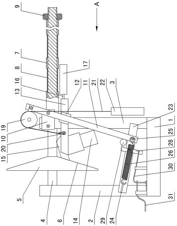
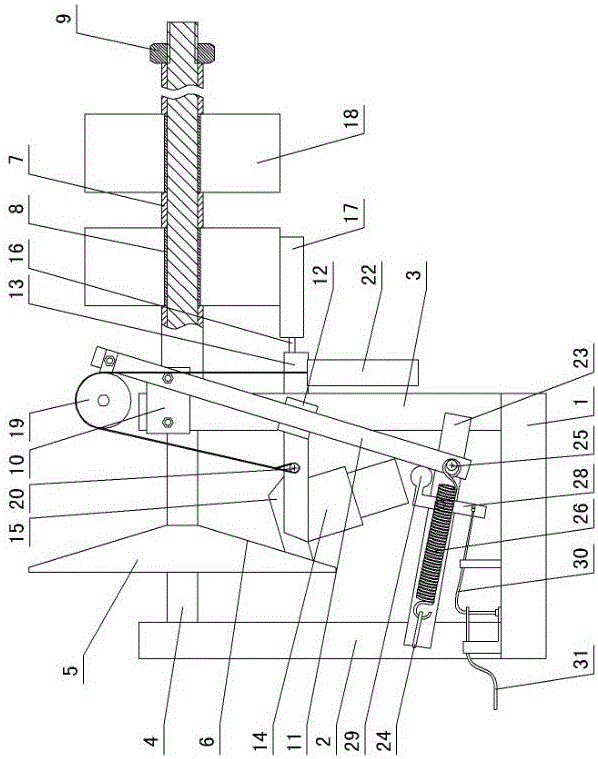
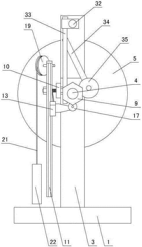
[0011] The invention relates to a constant-speed braided tape winding machine, such as figure 1 — Figure 4 Shown, it is characterized in that: comprise base 1, left support 2 and right support 3 are arranged on the base, drive shaft 4 is set between left and right support, friction wheel 5 is installed on the transmission shaft between left and right support, friction One side of the wheel is shaped on an oblique friction surface 6, and the outer wall of the transmission shaft outside the right support is provided with a compression ring 7 and a paper roll 8 at intervals, and a compression nut 9 is arranged at the end of the transmission shaft, and the compression nut is opposite to the compression ring and the paper roll 8. The paper rolls are pressed tightly, and a fixed block 10 is set on one side of the right bracket. An inclined slide rail 11 is arranged on the fixed block, and a slide block 12 is arranged on the inclined slide rail. Frame 13, fixed frame one side is pr...


PUM


Abstract

The invention discloses a constant speed woven belt winding machine. The constant speed woven belt winding machine is characterized by comprising a base, wherein a left bracket and a right bracket are arranged on the base; a transmission shaft is arranged between the left bracket and the right bracket; a friction wheel is mounted on the transmission shaft between the left bracket and the right bracket; an inclined friction surface is manufactured on one side of the friction wheel; a compression ring and a paper roll are arranged on the outer wall of the transmission shaft on the outer side of the right bracket at intervals; a compression nut is arranged at the end part of the transmission shaft; the compression nut compresses the compression ring and the paper roll; a fixing block is arranged on one side of the right bracket; an inclined slide rail is arranged on the fixing block; a sliding block is arranged on the inclined slide rail; the sliding block and the inclined slide rail are in sliding fit; a fixing rack is arranged on the sliding block; a motor is arranged on one side of the fixing rack; an output shaft of the motor is connected with a driving wheel manufactured through a rubber material; the driving wheel is in frictional contact with the inclined friction surface of the friction wheel; a rotating pin is manufactured on the other side of the fixing rack; a belt pressing wheel is arranged outside the rotating pin; and the belt pressing wheel is in contact with a woven belt on the outer wall of the paper roll.

Description

technical field [0001] The invention relates to a braided tape winder, in particular to a constant speed braided tape winder. Background technique [0002] After the existing woven tape is woven in the weaving machine, it is usually directly transported to the collection basket, and then the worker connects one end of the messy woven tape to the foot-operated tape winding machine. This tape winding machine mainly includes a frame. A turntable is set in the middle of the frame, and a rotating shaft is set in the middle of the turntable, and one end of the braided belt is connected to the rotating shaft, and the worker steps on the pedal to make the turntable rotate, and the turntable drives the rotating shaft to rotate, so that the braided belt is gradually rolled into a whole roll, which cannot be achieved by this structure. Automation, the labor intensity of workers is high, and the production efficiency is low. Therefore someone has invented the automatic tape winding mac...

Claims


Application Information

Patent Timeline
Patent Type & Authority Applications(China)
IPC IPC(8): B65H18/10B65H18/26B65H23/032B65H26/06B65H19/30
CPCB65H18/10B65H18/26B65H19/30B65H23/0324B65H26/06B65H2301/418B65H2701/1133
Inventor 沈传良
Owner 沈传良
Learn More