
Optical fiber stripping equipment and optical fiber stripping and cutting system

A cutting system and stripping technology, which is applied in the direction of light guide, optics, optical components, etc., can solve the problems of high labor cost, lifting, and difficulty in continuously and accurately controlling the length of the coating layer manually

Active Publication Date: 2020-07-10
GZ PHOTONICS CO LTD
View PDF11 Cites 3 Cited by
  • Summary
  • Abstract
  • Description
  • Claims
  • Application Information

AI Technical Summary

Problems solved by technology

[0003] At present, most laser companies still use wire strippers to manually strip the fiber coating layer, resulting in high labor costs, and it is difficult to continuously and accurately control the length of the coating layer stripped manually, which is not conducive to the improvement of fiber laser production efficiency.

Method used


Image

  • Optical fiber stripping equipment and optical fiber stripping and cutting system
  • Optical fiber stripping equipment and optical fiber stripping and cutting system
  • Optical fiber stripping equipment and optical fiber stripping and cutting system

Examples


other Embodiment approach

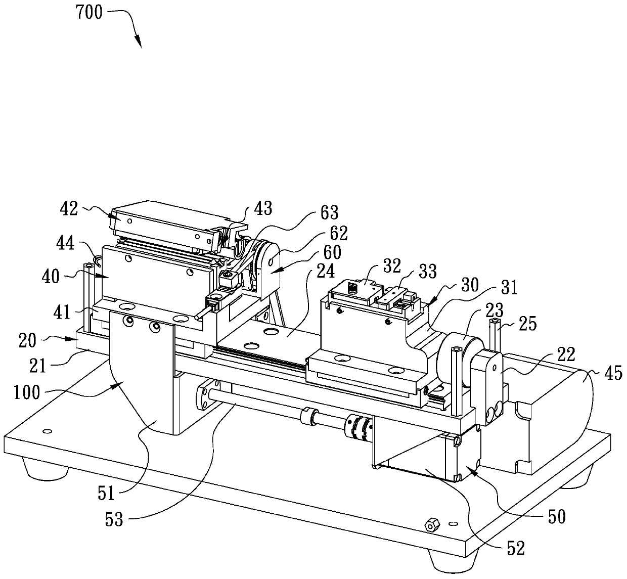
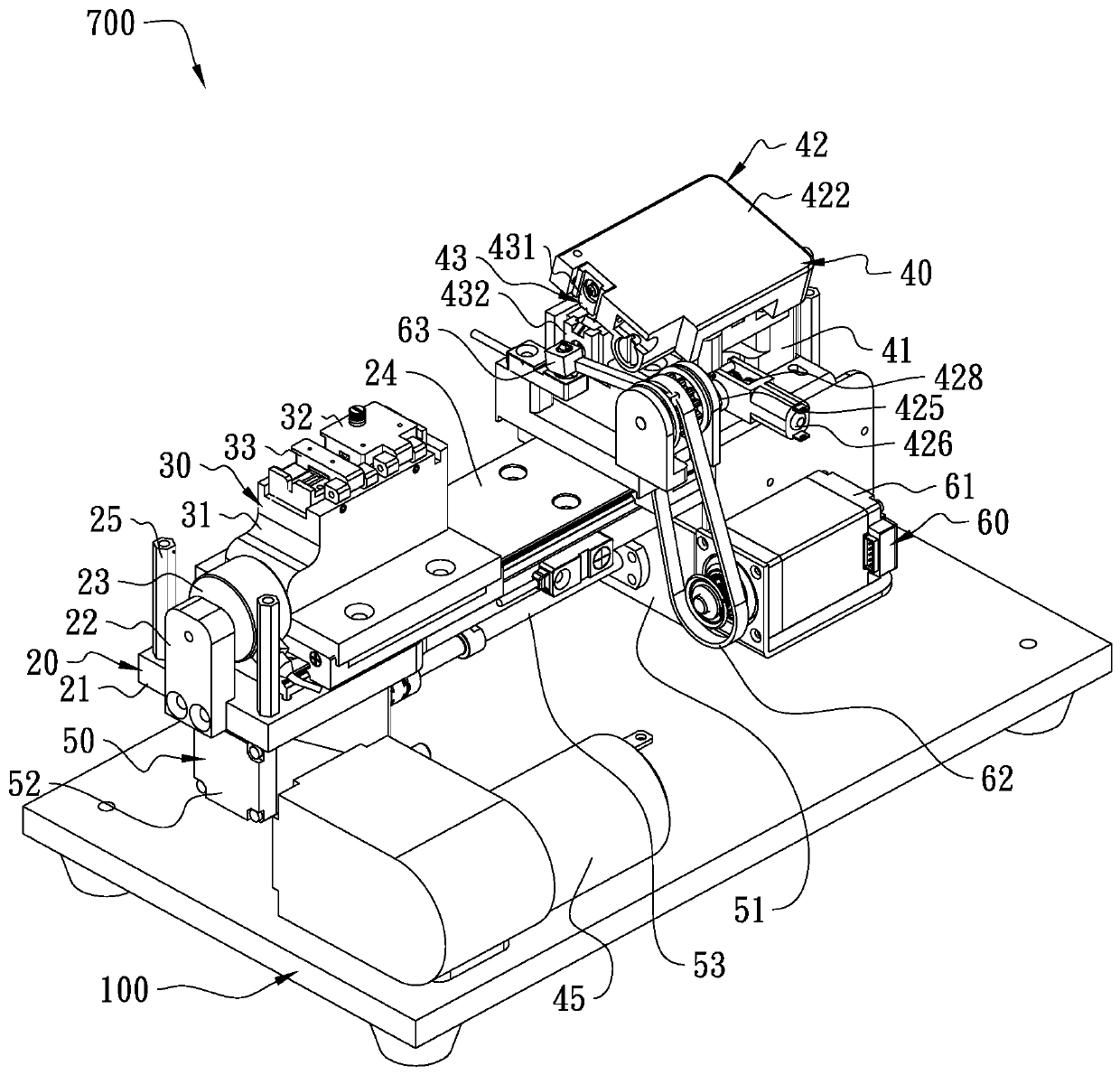
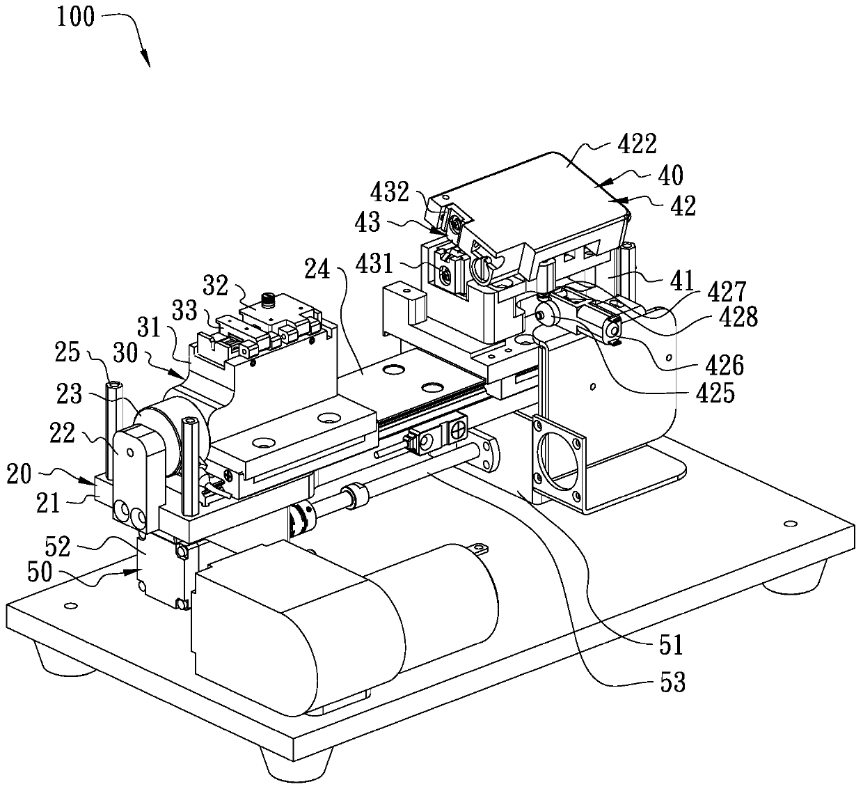
[0071] In other embodiments, in order to realize the compression and buffering of the optical fiber, a retractable cam with an elastic edge can also be used, and the deformation of the edge of the retractable cam can avoid a large pressure change on the optical fiber caused by the small rotation of the retractable cam 425 . In other implementation manners, the retractable ejector pin 427 can also be used to provide a buffering effect for the pressing of the optical fiber.

[0072] see Figure 10 , in one of the embodiments, the cutter device 60 includes a cutting driver 61 installed on the first base 41, a transmission mechanism 62 connected to the cutting driver 61, and a pendulum knife 63 installed on the transmission mechanism 62; the pendulum knife 63 There is a cutter head 631 on it; the cutting drive 61 drives the swing knife 63 to deflect through the transmission mechanism 62 ; the swing range of the cutter head 631 is between the blade stripping mechanism 43 and the c...


PUM


Abstract

The invention discloses optical fiber stripping equipment and an optical fiber stripping and cutting system. The optical fiber stripping equipment comprises a supporting device, a clamping device connected with the supporting device, a stripping device connected with the supporting device, and a transverse movement driving device used for driving the clamping device and the stripping device to beaway from each other. The clamping device is used for fixing part of the optical fiber. The stripping device comprises a first base installed on the supporting device, a folding mechanism installed onthe first base, and a stripping blade mechanism connected with the folding mechanism. The folding mechanism is used for driving the stripping blade mechanism to open and close. The stripping blade mechanism is used for scraping and stripping the coating layer. The folding mechanism or the blade stripping mechanism is used for positioning the optical fiber. The optical fiber is fixed on the clamping device, and then the other part of the optical fiber is positioned. Meanwhile, the folding mechanism enables the stripping blade mechanism to be attached to the coating layer of the optical fiber,then the stripping blade mechanism is far away from the clamping device through the transverse movement driving device, the coating layer of the optical fiber is separated from the fiber core under scraping and stripping of the stripping blade mechanism, and thus stripping of the coating layer is completed automatically.

Description

technical field [0001] The invention relates to an optical fiber processing device, in particular to an optical fiber stripping device and an optical fiber stripping and cutting system. Background technique [0002] With the rise of domestic lasers, the cost of imported lasers is constantly being forced down, which makes laser manufacturers have to find ways to reduce input costs in terms of incoming materials and manufacturing processes. Taking the fiber laser manufacturing process as an example, firstly, the fiber ends of multiple pump sources are fused with the input ends of the pump combiner one by one, and then the output ends of the pump combiner are fused with a series of optical fibers, and finally Then it is welded with the output head QBH of the laser, so that the entire optical path can be output completely. During the whole process, the corresponding optical fibers need to be spliced ​​several times, and the stripping of the fiber coating is a necessary process ...

Claims


Application Information

Patent Timeline
Patent Type & Authority Applications(China)
IPC IPC(8): G02B6/245G02B6/25
CPCG02B6/245G02B6/25
Inventor 蒲慧慧黄海利马修泉王楠楠
Owner GZ PHOTONICS CO LTD
Learn More