
Wharf water tank experiment structure applied to drilling platform and experiment method thereof

A technology for drilling platforms and water tanks, which is applied in the testing of machine/structural components, testing of mechanical components, measuring devices, etc. It can solve the problems of large water tanks, different sizes of water tanks, and inability to test them, etc., and achieve vertical height Enhanced effect

Inactive Publication Date: 2020-07-10
来安县祥瑞机电科技有限责任公司
View PDF8 Cites 0 Cited by
  • Summary
  • Abstract
  • Description
  • Claims
  • Application Information

AI Technical Summary

Problems solved by technology

[0006] The object of the present invention is to provide a kind of drilling platform application wharf water tank experimental structure and test method thereof, to solve the test device that the existing drilling platform application wharf water tank carries out endurance test in the above-mentioned background technology, when the water tank is tested due to the water tank The volume is large, and the test is basically to test the local area of ​​the water tank from various positions, rather than the entire water tank. The data obtained in this way are not comprehensive enough and there are many models of water tanks in different sizes. Once the water tank is too large, the vertical height reaches eight or nine meters. , the device cannot test it, and there are limitations

Method used


Image

  • Wharf water tank experiment structure applied to drilling platform and experiment method thereof
  • Wharf water tank experiment structure applied to drilling platform and experiment method thereof
  • Wharf water tank experiment structure applied to drilling platform and experiment method thereof

Examples


Embodiment Construction

[0036] In the description of the present invention, it should be noted that the terms "center", "upper", "lower", "left", "right", "vertical", "horizontal", "inner", "outer" etc. The indicated orientation or positional relationship is based on the orientation or positional relationship shown in the drawings, and is only for the convenience of describing the present invention and simplifying the description, rather than indicating or implying that the referred device or element must have a specific orientation, or in a specific orientation. construction and operation, therefore, should not be construed as limiting the invention. In addition, the terms "first", "second", and "third" are used for descriptive purposes only, and should not be construed as indicating or implying relative importance.

[0037] In the description of the present invention, it should be noted that unless otherwise specified and limited, the terms "installation", "connection" and "connection" should be un...


PUM


Abstract

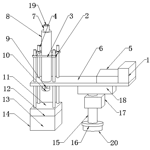
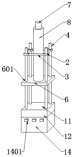
The invention discloses a wharf water tank experiment structure applied to a drilling platform and an experiment method thereof. The structure comprises a hydraulic column control box bottom plate anda hydraulic column. A reinforcing block and a fixing frame are arranged at the top of the bottom plate of the hydraulic column control box. A hydraulic column control box is mounted on one side of the reinforcing block. A through hole penetrates through the joint of the fixing frame and the bottom plate of the hydraulic column control box. An alloy pressurizing plate is mounted at the bottom of the fixing frame. A water tank placing table is arranged in the center of the alloy pressurizing plate. A hydraulic pusher is mounted at the bottom of the alloy pressurizing plate. A switch fixing plate is arranged on the side surface of the hydraulic pusher. A pressurization control switch is embedded into the outer surface of the switch fixing plate. Through the arrangement of the water tank placing table, the hydraulic pusher and the hydraulic column, the problems that when the device tests the water tank, due to the fact that the size of the water tank is large, the test is basically conducted on the local area of the water tank from all positions, the whole water tank is not tested, and obtained data is not comprehensive enough are solved.

Description

technical field [0001] The invention relates to the technical field of water tank durability tests, in particular to a water tank test structure and a test method for a drilling platform application wharf. Background technique [0002] The drilling platform is an offshore structure mainly used for drilling wells. The platform is equipped with drilling, power, communication, navigation and other equipment, as well as safety and lifesaving and personnel living facilities. It is an indispensable means of offshore oil and gas exploration and development. The drilling platform is actually equivalent to Applied to offshore docks, multiple water tanks are generally placed on the drilling platform. The water tanks are divided into six types according to the material: glass fiber reinforced plastic water tanks, stainless steel water tanks, stainless steel liner glass steel water tanks, seawater glass steel water tanks, enamel water tanks, and galvanized steel water tanks. Water tanks ...

Claims


Application Information

Patent Timeline
IPC IPC(8): G01M13/00
CPCG01M13/00
Inventor 张玉开
Owner 来安县祥瑞机电科技有限责任公司
Learn More