Inflatable maintenance-free tire
A maintenance-free, tire-free technology, applied to tire inflation valves, tire parts, and independent air cushions, etc., can solve the problems of reduced tire service life, slow air leakage that needs to be inflated in time, and driving without air pressure, etc., to achieve Wear evenly, improve comfort performance, and improve the effect of wrapping
- Summary
- Abstract
- Description
- Claims
- Application Information
AI Technical Summary
Problems solved by technology
Method used
Image
Examples
Embodiment 1
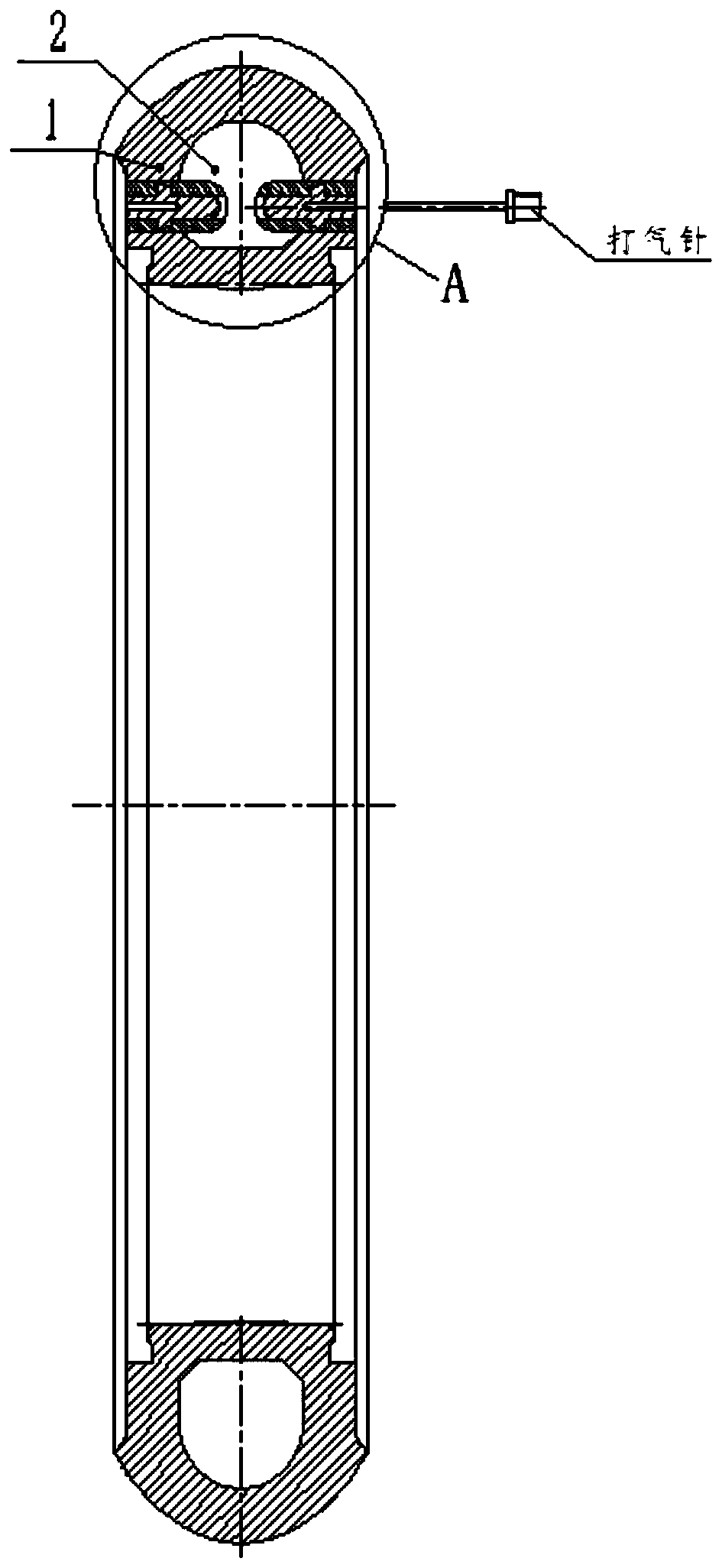
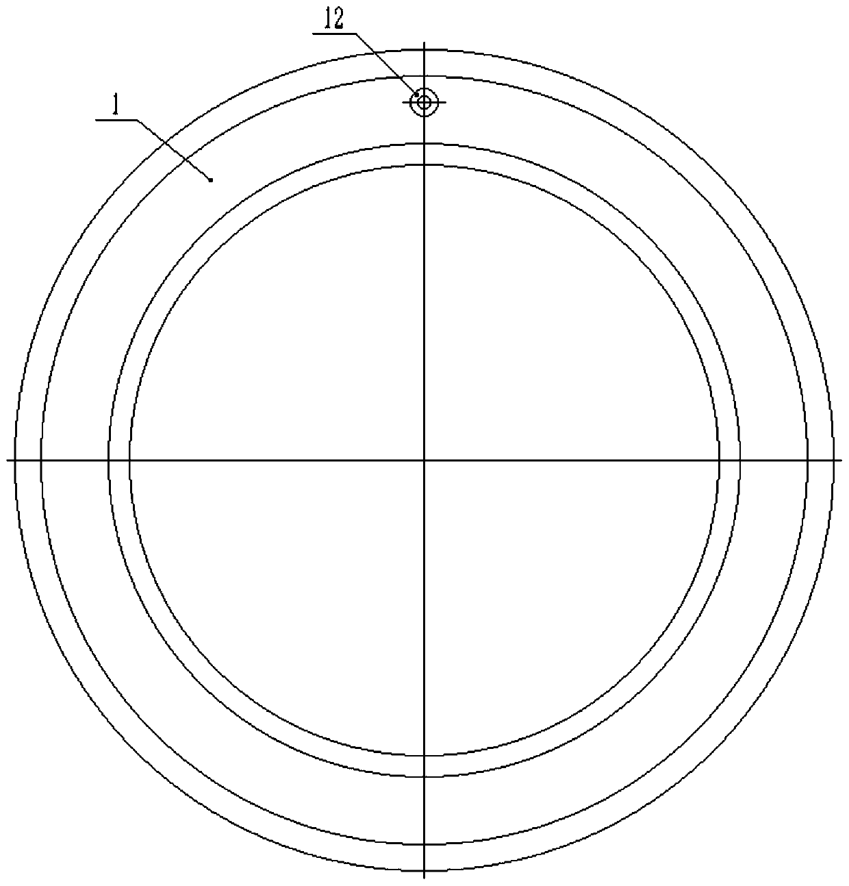
[0033] like figure 1 and 2 As shown, an inflatable maintenance-free tire includes a tire body 1, the top side of the tire body 1 is a crown 3, the inner side of the tire body 1 is a placenta 4, and between the tire crown 3 and the placenta 4 is fetal wall. The tire body 1 is provided with a sealed inner cavity 2, and the tire body 1 is provided with a valve 12 for inflating or deflated the inner cavity 2. In this embodiment, the air valve 12 is arranged on the tire wall.
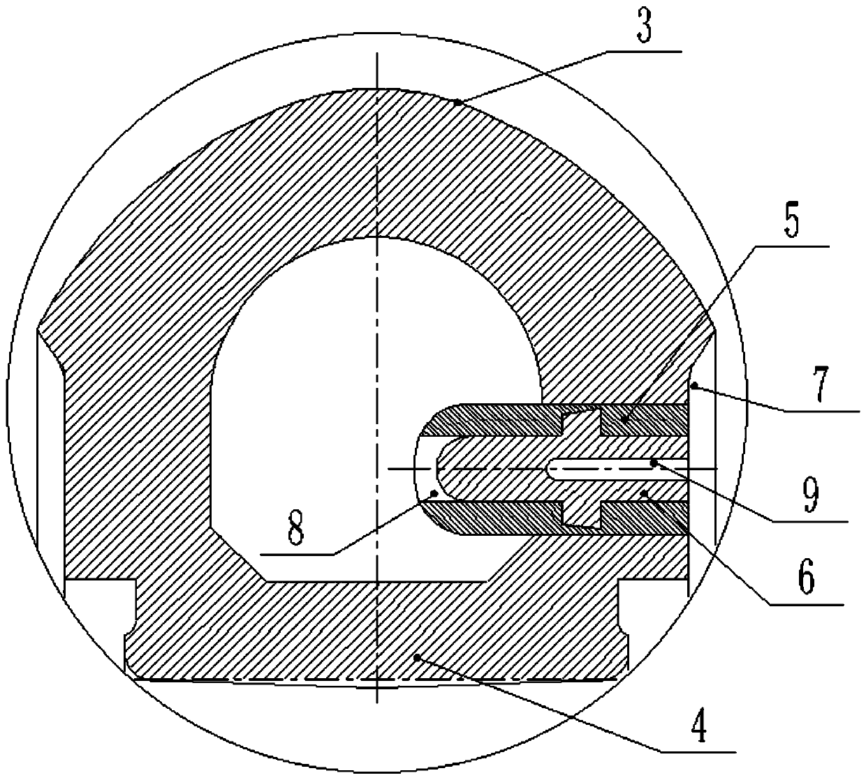
[0034] In this example, if image 3 As shown, the valve 12 includes a male nozzle 6 and a female nozzle 5. The female nozzle 5 is embedded in the tire wall, preferably vertically arranged. channel 8 , the male nozzle 6 is engaged in the airflow channel 8 , so that the male nozzle 6 and the female nozzle 5 are sealed.
[0035] like Figure 4 and 5 As shown, the specific engaging method is: the side wall of the air flow channel 8 of the female nozzle 5 is provided with a card slot 11, the side wall of t...
Embodiment 2
[0047] This embodiment is further optimized on the basis of Embodiment 1, and the similarities will not be repeated. In this embodiment, several pattern grooves are set on the crown 3, and the valve 12 is arranged on the pattern grooves of the crown 3. inside, such as Figure 7 and 8 shown.
Embodiment 3
[0049] This embodiment is further optimized on the basis of Embodiment 1, and the similarities will not be repeated. In this embodiment, the tire wall is provided with an escape groove 7 in the direction of the inner cavity 2 at the lower part of the carcass, and the valve 12 It is arranged on the side wall of the avoidance groove 7. The escape groove 7 is provided to protect the structure of the air valve 12 .
PUM
 Abstract
Description
Claims
Application Information
 - R&D
- Intellectual Property
- Life Sciences
- Materials
- Tech Scout
- Unparalleled Data Quality
- Higher Quality Content
- 60% Fewer Hallucinations
Browse by: Latest US Patents, China's latest patents, Technical Efficacy Thesaurus, Application Domain, Technology Topic, Popular Technical Reports.
© 2025 PatSnap. All rights reserved.Legal|Privacy policy|Modern Slavery Act Transparency Statement|Sitemap|About US| Contact US: help@patsnap.com


