
Battery diaphragm manufacturing device based on phase separation method

A technology of battery diaphragm and phase separation method, which is applied in battery pack parts, circuits, electrical components, etc., can solve problems such as affecting the production of diaphragms and large temperature difference

Active Publication Date: 2020-07-10
乐清泰起知识产权服务有限公司
View PDF3 Cites 0 Cited by
  • Summary
  • Abstract
  • Description
  • Claims
  • Application Information

AI Technical Summary

Problems solved by technology

[0003] The existing wet method is to mix liquid hydrocarbons or some small molecular substances with polyolefin resin, heat and melt to form a uniform mixture, then cool down to separate phases, press to obtain a membrane, and then carry out bidirectional stretching to orient the molecular chain. Finally, the film material is obtained; while the existing wet process equipment uses different mechanisms to process the compression and stretching of the diaphragm, resulting in a large temperature difference between the surfaces of different mechanisms, which will make the diaphragm surface act on it. The diaphragm produces different degrees of shrinkage, which affects the production of the diaphragm, so a battery diaphragm production equipment based on the phase separation method came into being

Method used


Image

  • Battery diaphragm manufacturing device based on phase separation method
  • Battery diaphragm manufacturing device based on phase separation method
  • Battery diaphragm manufacturing device based on phase separation method

Examples


Embodiment Construction

[0022] The technical solutions in the embodiments of the present invention will be clearly and completely described below with reference to the accompanying drawings in the embodiments of the present invention. Obviously, the described embodiments are only a part of the embodiments of the present invention, but not all of the embodiments. Based on the embodiments of the present invention, all other embodiments obtained by those of ordinary skill in the art without creative efforts shall fall within the protection scope of the present invention.

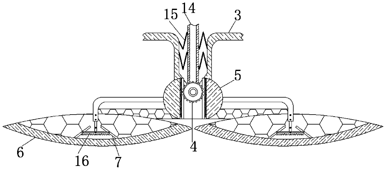
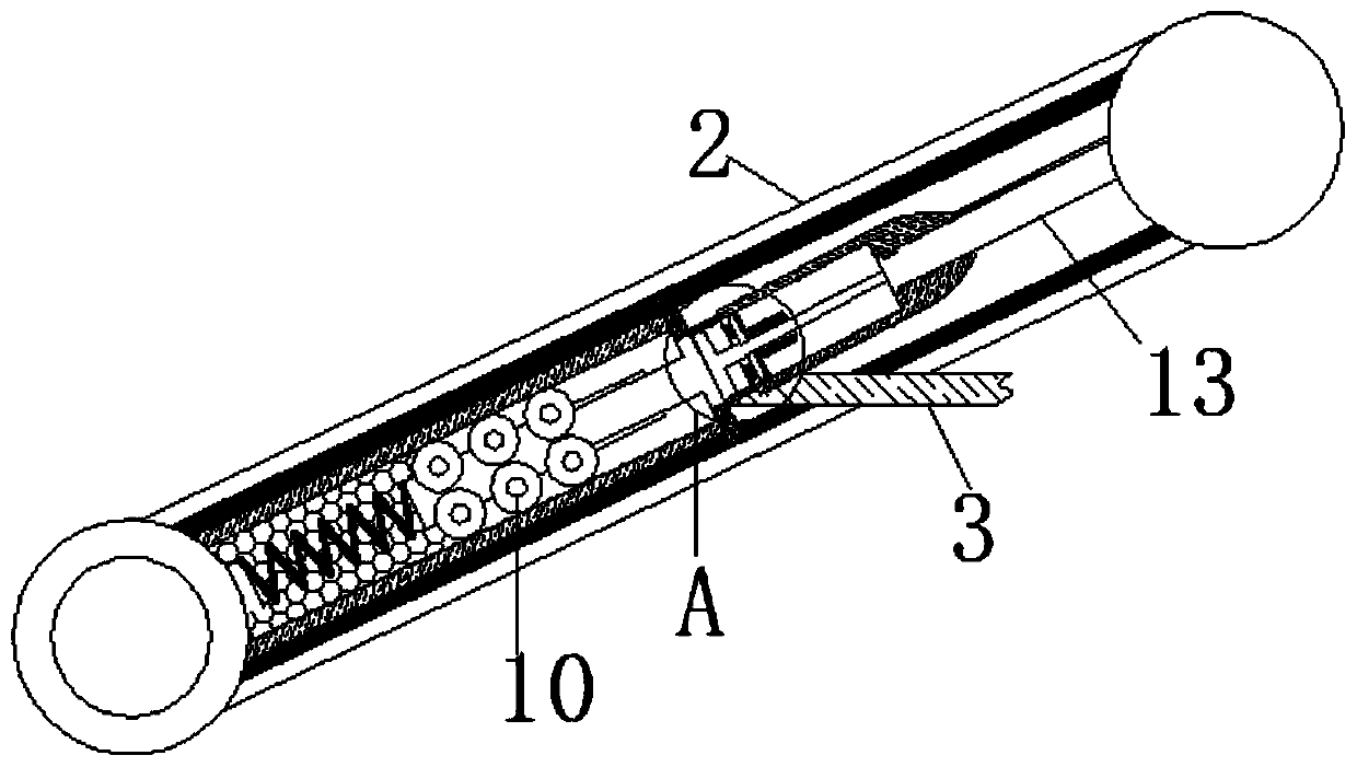
[0023] see Figure 1-5 , a battery separator manufacturing equipment based on the phase separation method, including a push rod 1, the lower end of the push rod 1 is movably connected with a stretch rod 2, the number of the stretch rod 2 is two, and the symmetrical pull rope rods 2 The distance and the elastic force range of back-moving spring 15 are adapted;

[0024] The end of the return spring 15 away from the delivery pipe 14 is ...


PUM


Abstract

The invention relates to the technical field of battery diaphragm manufacturing, and discloses a battery diaphragm manufacturing device based on a phase separation method. The battery diaphragm manufacturing device based on the phase separation method comprises a push rod, the lower end of the push rod is movably connected with a stretching rod, the surface of the stretching rod is movably connected with a twisting plate, the bottom of the twisting plate is movably connected with a gear, the surface of the gear is movably connected with an engagement plate, the side, away from the gear, of the engagement plate is movably connected with a pressing plate, a pushing part is movably connected into the pressing plate, a liquid storage bladder is movably connected into the stretching rod, a compression spring is movably connected into the liquid storage bladder, the surface of the compression spring is movably connected with a roller rod, a deflection plate is slidably connected to the end,away from the compression spring, of the roller rod, and the surface of the deflection plate is movably connected with a spring tube. The squeezing work of a diaphragm is carried out, with the continuous movement of the push rod, the stretching rod gradually moves to two sides, and the stretching work of the diaphragm is carried out, so that the effect of using the same mechanism to reduce the effect of temperature difference on the diaphragm is achieved.

Description

technical field [0001] The invention relates to the technical field of battery diaphragm production, in particular to a battery diaphragm production equipment based on a phase separation method. Background technique [0002] The battery diaphragm refers to a layer of diaphragm material between the positive and negative electrodes of the battery. It is a very critical part of the battery and has a direct impact on battery safety and cost. Its main function is to isolate the positive and negative electrodes and prevent the electrons in the battery from Freely pass through, allowing the ions in the electrolyte to pass freely between the positive and negative electrodes; the preparation methods of battery separators are divided into two types: dry method and wet method, among which wet method is used more. [0003] The existing wet method is to mix liquid hydrocarbons or some small molecular substances with polyolefin resin, heat and melt to form a uniform mixture, then cool dow...

Claims


Application Information

Patent Timeline
Patent Type & Authority Applications(China)
IPC IPC(8): B29C69/02B29C33/72H01M2/14B29L7/00
CPCB29C33/72B29C69/02B29L2007/002H01M50/403Y02E60/10
Inventor 葛兆胜
Owner 乐清泰起知识产权服务有限公司
Learn More