
Equipment for positioning and manufacturing stator in motor energized coil

A technology for energized coils and stators, which is used in the manufacture of stator/rotor bodies, metal processing equipment, grinding/polishing equipment, etc., which can solve the problems of destroying materials and increasing the force load on the surface of silicon steel sheets.

Active Publication Date: 2020-07-07
ZHEJIANG HMC
View PDF14 Cites 2 Cited by
  • Summary
  • Abstract
  • Description
  • Claims
  • Application Information

AI Technical Summary

Problems solved by technology

[0003] In the prior art, silicon wafers are often drilled in sequence for the production of energized coils, and then installed. Although this method has high manufacturing accuracy, because the electrical conductivity of the silicon steel sheet is affected by its surface roughness, it is difficult to drill. The hole needs to be polished and polished. The existing technology uses manual or mechanical hands to process this. Using the above-mentioned processing method, the silicon steel sheet needs to be transferred and re-clamped, and the transfer and clamping will increase the surface area of ​​the silicon steel sheet. The force load on the surface will destroy the material on its surface, so a stator device in the energized coil of the positioning motor emerges as the times require

Method used

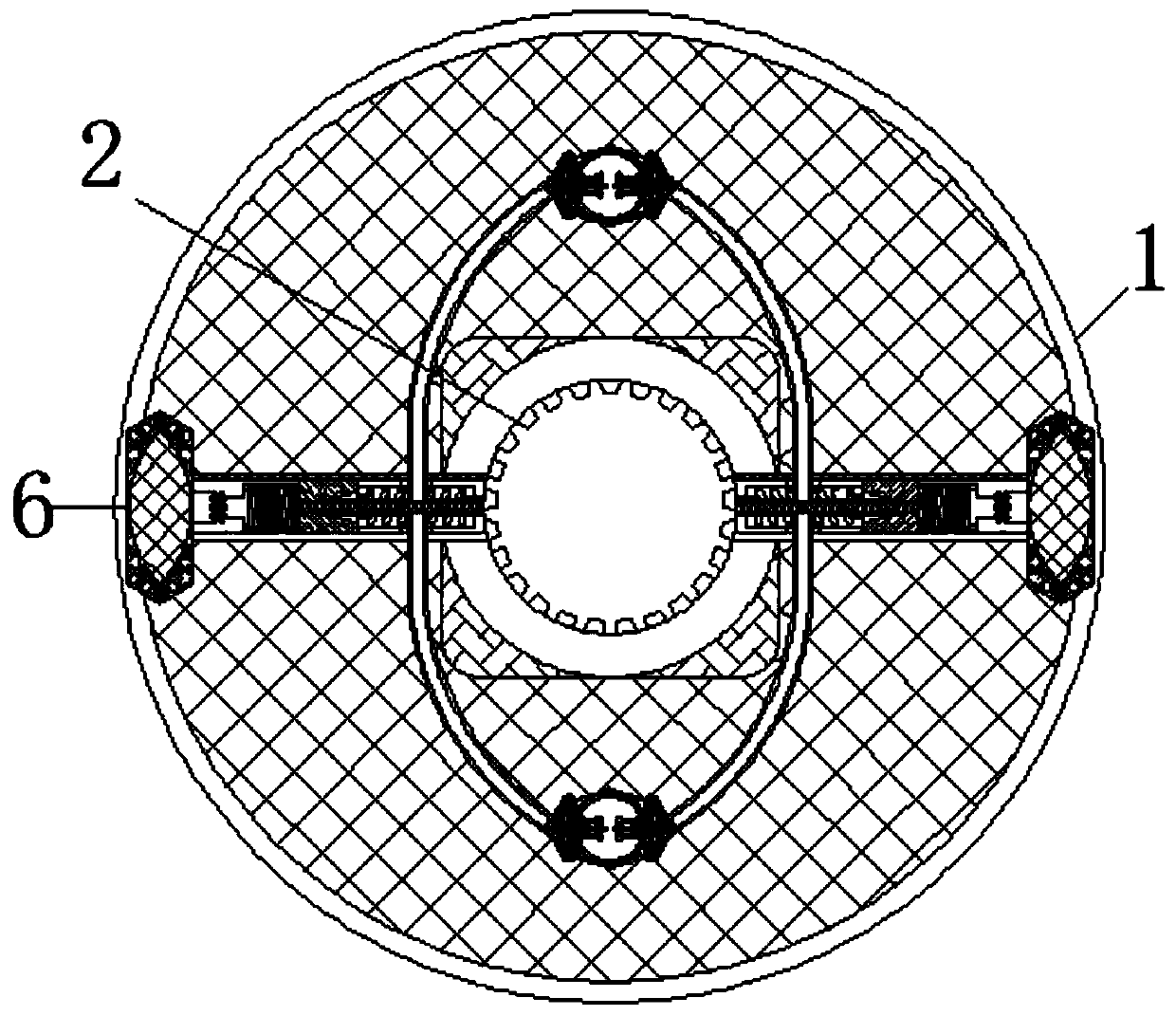
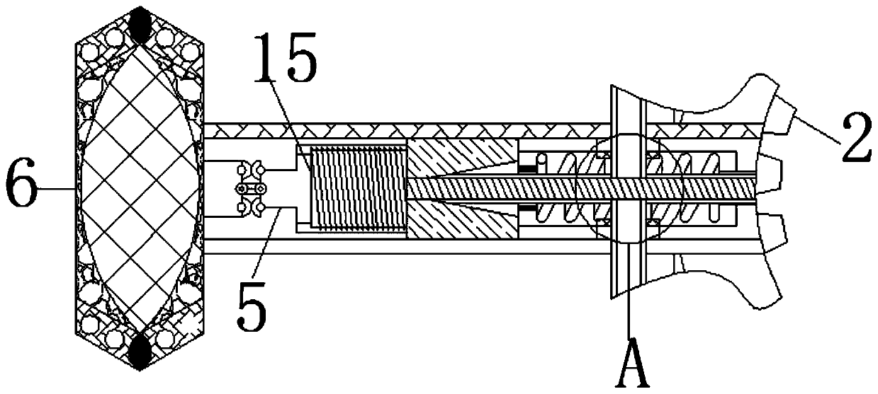
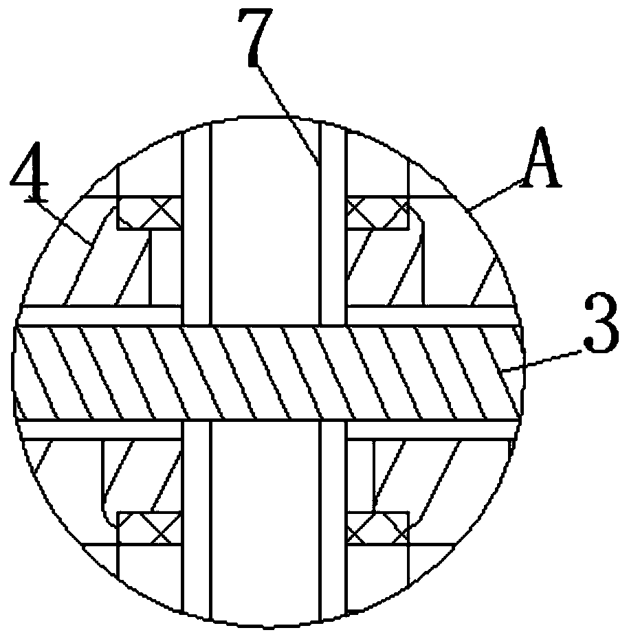

Image

  • Equipment for positioning and manufacturing stator in motor energized coil
  • Equipment for positioning and manufacturing stator in motor energized coil
  • Equipment for positioning and manufacturing stator in motor energized coil

Examples


Embodiment Construction

[0023] The following will clearly and completely describe the technical solutions in the embodiments of the present invention with reference to the accompanying drawings in the embodiments of the present invention. Obviously, the described embodiments are only some, not all, embodiments of the present invention. Based on the embodiments of the present invention, all other embodiments obtained by persons of ordinary skill in the art without making creative efforts belong to the protection scope of the present invention.

[0024] see Figure 1-7 , a device for positioning and manufacturing the stator in the energized coil of the motor, including the turntable 1, the size of the turntable 1 is smaller than the size of the silicon wafer, and 160,000 transistors can be integrated on the silicon wafer as large as a grain of rice, which is another milestone in the progress of science and technology Milestone, the silicon element with a content of 25.8% in the earth's crust provides a...


PUM


Abstract

The invention relates to the technical field of manufacturing of electrified coils in motors, and discloses equipment for positioning and manufacturing a stator in a motor energized coil. The equipment comprises a rotary disc, wherein the surface of the rotary disc is movably connected with a gear; the surface of the gear is movably connected with a screw rod; the surface of the screw rod is movably connected with an extension spring; the surface of the extension spring is movably connected with a movable rod; the end, away from the extension spring, of the movable rod is movably connected with a grinding disc. A connecting rod is movably connected to the joint of the screw and the extension spring, an expansion plate is movably connected to the end, away from the screw, of the connectingrod, a torsion spring is movably connected to the surface of the expansion plate, a guide shaft is movably connected to the surface of the torsion spring, a rotating plate is movably connected to thesurface of the guide shaft, and a hole expanding plate is movably connected to the surface of the rotating plate. And if the hole grinding size is perfect, the detection bag does not contact with thehole, otherwise, the detection bag contacts with the hole to generate gas, so the effects of grinding and polishing the silicon wafer and detecting the aperture are achieved.

Description

technical field [0001] The invention relates to the technical field of manufacturing energized coils in motors, in particular to a device for positioning and manufacturing stators in energized coils in motors. Background technique [0002] The motor is a device that converts electrical energy into mechanical energy. It uses a energized coil to generate a rotating magnetic field and acts on the rotor to form a magnetoelectric rotational torque. The energized coil is usually composed of several punching sheets, and the punching material is usually silicon steel sheet Among them, the silicon steel sheet is a thin steel plate with a very low carbon content and has good electrical conductivity. [0003] In the prior art, silicon wafers are often drilled in sequence for the production of energized coils, and then installed. Although this method has high manufacturing accuracy, because the electrical conductivity of the silicon steel sheet is affected by its surface roughness, it i...

Claims


Application Information

Patent Timeline
IPC IPC(8): H02K15/02B24B5/48G01B5/12
CPCB24B5/48G01B5/12H02K15/02
Inventor 周敏
Owner ZHEJIANG HMC
Learn More