


Quick Research
Generate reliable direction feasibility study reports for your R&D in just a few steps.

Technical Q&A
Discover and master advanced knowledge NOW. Basics, ideas, possibilities, all at once.

Find Solutions
As an expert in R&D theories, this can generate solutions to your technical problems instantly.

Evaluate Feasibility
Analyze your overall solution with one click, know your potential R&D risks in advance.

Monitor Landscape
Get weekly tech updates, stay abreast of the latest tech innovations and key insights.
Battery pack cooling system and vehicle
A cooling system and battery pack technology, applied in electric vehicles, vehicle components, vehicle energy storage, etc., can solve problems such as large space occupation, complex layout, and danger
- Summary
- Abstract
- Description
- Claims
- Application Information
AI Technical Summary
Problems solved by technology
Method used
Image


Examples
Embodiment 1
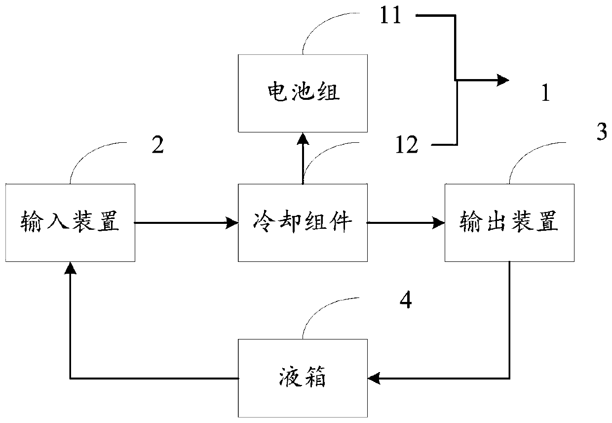
[0031] Embodiment 1 provides a battery pack cooling system, combined with figure 1 with image 3 As shown, the system includes: a plurality of battery packs 1, an input device 2 and an output device 3; the battery pack 1 includes a battery pack 11 and a cooling assembly 12, and the battery packs 11 in the multiple battery packs 1 are Stacking, the cooling components 12 in the multiple battery packs 1 are independent of each other, and the cooling components 12 are used to ensure that the battery packs 11 are cooled independently, which can avoid temperature interference between the cooling components, and also avoid one of them. When the cooling component is damaged, the cooling capacity of other cooling components will not be affected, ensuring the cooling effect;
[0032] One end of the cooling assembly 12 is connected to the input device 2, and the other end of the cooling assembly 2 is connected to the output device 3 to form a cooling path. The input device 2 is used to ...
Embodiment 2
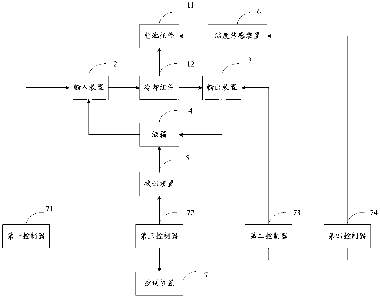
[0047] The second embodiment provides a battery pack cooling system, combining figure 2 with image 3As shown, the system includes: a plurality of battery packs 1, an input device 2 and an output device 3; the battery pack 1 includes a battery pack 11 and a cooling assembly 12, and the battery packs 11 in the multiple battery packs 1 are Stacking, the cooling components 12 in the multiple battery packs 1 are independent of each other, and the cooling components 12 are used to ensure that the battery packs 11 are cooled independently, which can avoid temperature interference between the cooling components, and also avoid one of them. When the cooling component is damaged, the cooling capacity of other cooling components will not be affected, ensuring the cooling effect;
[0048] One end of the cooling assembly 12 is connected to the input device 2, and the other end of the cooling assembly 2 is connected to the output device 3 to form a cooling path. The input device 2 is use...
PUM
 Abstract
Description
Claims
Application Information
 - R&D Engineer
- R&D Manager
- IP Professional
- Industry Leading Data Capabilities
- Powerful AI technology
- Patent DNA Extraction
Browse by: Latest US Patents, China's latest patents, Technical Efficacy Thesaurus, Application Domain, Technology Topic, Popular Technical Reports.
© 2024 PatSnap. All rights reserved.Legal|Privacy policy|Modern Slavery Act Transparency Statement|Sitemap|About US| Contact US: help@patsnap.com