
Heavy oil hydrogenation system and a hydrogenation method capable of self-producing hydrogen

A heavy oil hydrogenation and hydrogen technology, applied in the field of oil refining and chemical industry, can solve the problems of poor device integration, large device load, and complicated operation

Active Publication Date: 2020-07-07
CHINA PETROLEUM & CHEM CORP +1
View PDF5 Cites 0 Cited by
  • Summary
  • Abstract
  • Description
  • Claims
  • Application Information

AI Technical Summary

Problems solved by technology

However, this patent still requires new hydrogen compressors and circulating hydrogen compressors, and the device integration is poor; and multiple hydrogenation devices sharing a new hydrogen compression system will cause excessive load on the device, and multiple compressors have to be used. It is difficult to adjust the load of the device and the operation is extremely complicated

Method used


Image

  • Heavy oil hydrogenation system and a hydrogenation method capable of self-producing hydrogen
  • Heavy oil hydrogenation system and a hydrogenation method capable of self-producing hydrogen
  • Heavy oil hydrogenation system and a hydrogenation method capable of self-producing hydrogen

Examples


Embodiment 1

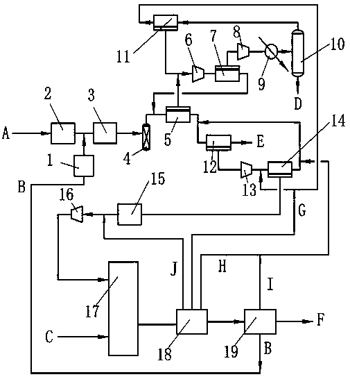
[0049] The flow chart of this embodiment is attached figure 1 . Raw coal A is pulverized and dust-removed and then pneumatically conveyed into the coal gasification reaction unit 2, and the hydrogenated tail oil B from the fractionation unit 19 enters the heavy oil gasification reaction unit 1. The heavy oil gasification reaction unit 1 and the coal gasification reaction unit 2 adopt fluidized bed reactors. In the coal gasification reaction unit 2, the pulverized coal is converted into coal gas, carbon dioxide, etc. during the rising process through the lifting of the transport gas and oxygen, and then the ash is removed by water washing, and the deep conversion is carried out. The reaction temperature of coal gasification reaction unit 2 is 1475°C, the pressure is 3.85MPa, and the space velocity is 10h -1 . The generated gas from the coal gasification reaction unit 2 enters the water gas shift reaction unit 3 for a shift reaction to convert water vapor into hydrogen. The ...

Embodiment 2

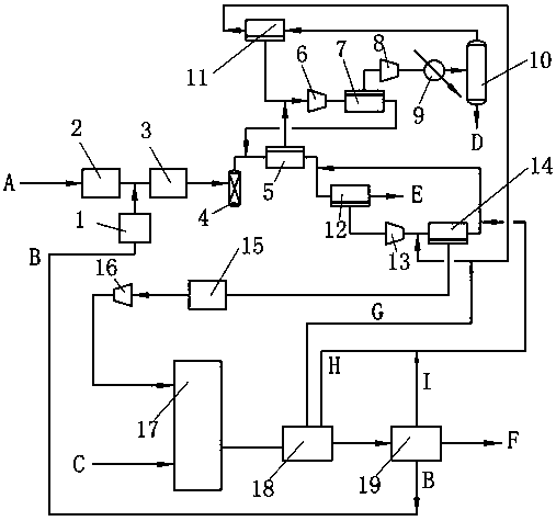
[0056] The flow chart of this embodiment is attached figure 2 . Compared with the flow process of Example 1, this example differs in that the heavy oil hydrogenation reaction unit includes two reaction zones connected in series, the first reaction zone and the second reaction zone, and one ebullating bed reactor is set in each reaction zone , the first ebullating bed reactor discharges the sulfur-rich flash gas G from the top, and the second ebullating bed reactor discharges the hydrogen-rich flash gas H from the top; the flash gas G enters the second hydrogen separation membrane 14; the flash gas H and the second The retentate gas from the hydrogen separation membrane 14 returns to the inlet of the first hydrogen separation membrane 12 after merging.

[0057] The operating temperature of the first ebullating bed reactor and the second ebullating bed reactor is 400°C, and the hydrogenation conversion rate of residual oil is 60%. Hydrogen feedstock.

[0058] The material ba...


PUM


Abstract

The invention discloses a heavy oil hydrogenation system and a hydrogenation method capable of self-producing hydrogen. The heavy oil hydrogenation system comprises a coal gasification reaction unit,a heavy oil gasification reaction unit, a water-gas shift reaction unit, a three-stage carbon dioxide separation membrane, a two-stage hydrogen separation membrane, a four-stage compression unit, a liquid separation tank, a filtering unit, a condensation unit, a desulfurization unit, a heating unit, a heavy oil hydrogenation reaction unit and a fractionation unit. The invention also discloses a hydrogenation method by adopting the system. According to the heavy oil hydrogenation system and the hydrogenation method, the hydrogen partial pressure can be greatly improved, the hydrogenation reaction efficiency and the product quality are further improved, meanwhile, carbon dioxide is a byproduct, and carbon emission of a hydrogenation device is reduced.

Description

technical field [0001] The invention belongs to the technical field of oil refining and chemical industry, and in particular relates to a hydrogenation system and a hydrogenation method for hydrogen self-sufficiency. Background technique [0002] Due to its viscous nature and high impurity content, inferior heavy oil is easy to coke and generate carbon. Under the restriction of increasingly stringent product requirements and environmental protection regulations, it has become a petroleum component with low added value and difficult to utilize. Hydrogenation is an effective means of upgrading and converting heavy oil. Large and medium-sized refineries often need 1.5-5 million tons / year hydrogenation units to meet the demand for heavy oil conversion. Based on the hydrogen consumption of 1%-1.5%, the increased hydrogen consumption of the refinery can reach 2-7.5 10,000 tons / year. [0003] In order to meet the hydrogen demand of the hydrogenation unit, the low-cost hydrogen p...

Claims


Application Information

Patent Timeline
IPC IPC(8): C10G67/02
CPCC10G67/02C10G2300/4006C10G2300/4012C10G2300/4043C10G2300/4081Y02P30/40
Inventor 陈博孟兆会葛海龙杨涛蒋立敬
Owner CHINA PETROLEUM & CHEM CORP
Learn More