
Ink-jet printing trolley and ink-jet printing device

A technology for inkjet printing and ink supply devices, which is applied in printing devices, printing, typewriters, etc., and can solve problems such as weight increase, printing car structure stress mode and running stability discount, nozzle nozzle precision splicing problems, etc.

Pending Publication Date: 2020-07-07
선전진신테크놀로지컴퍼니리미티드
View PDF0 Cites 9 Cited by
  • Summary
  • Abstract
  • Description
  • Claims
  • Application Information

AI Technical Summary

Problems solved by technology

[0002] In the prior art, the inkjet printing trolley of the circuit board inkjet printing equipment generally adopts a cantilever structure, and by scanning back and forth on the internal beam of the equipment, the ink droplets are sprayed onto the printing medium on the printing table below the beam to realize the printing of images or text , as printing media tends to be more and more large-format production, in order to improve the work efficiency of inkjet printing equipment when printing graphics and text on one side of large-format printing media, it is necessary to set a larger number of nozzles to print at the same time. However, according to the existing design method of the printing carriage, the number of nozzles is doubled and the cantilever of the carriage is lengthened, the structural span of the carriage will become larger and the weight will increase accordingly, which makes the stress mode and operation of the printing carriage structure stable The performance is greatly reduced, and it cannot meet the requirements of inkjet printing well, and the installation of nozzles and the precision splicing between nozzles have also become a major problem.

Method used


Image

  • Ink-jet printing trolley and ink-jet printing device
  • Ink-jet printing trolley and ink-jet printing device
  • Ink-jet printing trolley and ink-jet printing device

Examples


Embodiment Construction

[0033] The present invention will be described in detail below with reference to the drawings and specific embodiments.

[0034] It should be noted that all directional indications (such as up, down, left, right, front, back...) in the embodiment of the present invention are limited to relative positions on the designated view, not absolute positions.

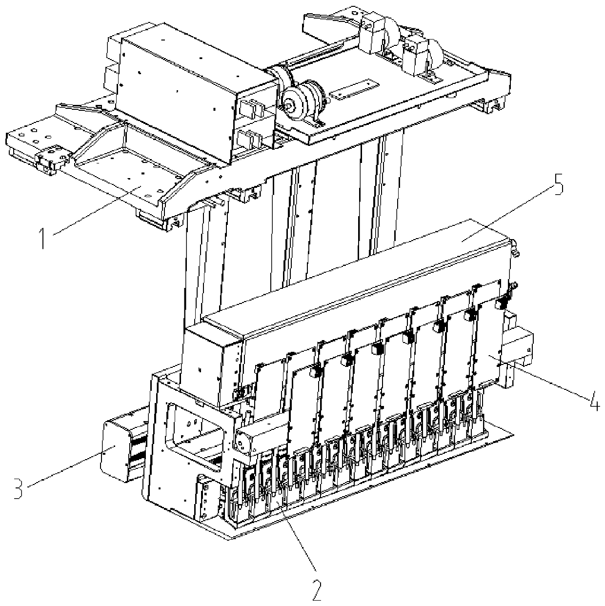
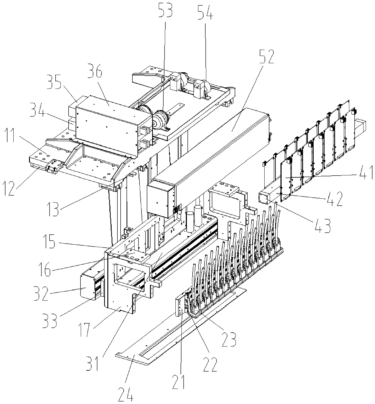
[0035] See Figure 1 to Figure 3 , The present invention provides an inkjet printing cart, which includes: a cart support assembly 1, a printing module 2, a curing module 3, a nozzle control module 4, and an ink supply device 5. The trolley support assembly 1 is slidably installed on the beam of the equipment, and is used to carry the printing module 2, the curing module 3, the nozzle control module 4 and the ink supply device 5. The jet printing module 2 is used to print graphics and text on the printing medium, which can meet the printing requirements of different wide-format printing media. The curing module 3 is used for curin...


PUM


Abstract

The invention discloses an ink-jet printing trolley and an ink-jet printing device. The ink-jet printing trolley comprises a trolley support assembly, an ink-jet printing module, a curing module, a spray head control module and an ink supply device. The trolley support assembly is slidably arranged on an equipment cross beam for bearing the ink-jet printing module, the curing module, the spray head control module and the ink supply device. The ink-jet printing module is sued for printing images and texts on a printing medium. The curing module is used for curing the printed images and texts. The spray head control module is used for controlling the ink-jet printing module to print. The ink supply device is used for supplying ink to the ink-jet printing module. Relatively more spray heads can be loaded conveniently and rapidly, so that a relatively wider circuit board can be covered by single scanning of the trolley. The quantity of the arranged spray heads can be changed according to actual demand, and the printing demands on different width circuit boards can be met. The ink-jet printing trolley is balanced in structural stress and stable to operate, and can guarantee printing with high efficiency and high quality. The modules are conveniently detached and maintained at ordinary time.

Description

Technical field [0001] The invention relates to the technical field of printing equipment, in particular to an inkjet printing cart and an inkjet printing device. Background technique [0002] In the prior art, the inkjet printing trolley of the circuit board inkjet printing equipment generally adopts a cantilever structure. The ink droplets are ejected onto the printing medium on the printing table below the crossbeam by scanning back and forth on the beam inside the device to realize the printing of images or text. , As the printing medium is becoming more and more large-format production, in order to improve the working efficiency of inkjet printing equipment when printing a large-format printing medium, it is necessary to set a larger number of nozzles to simultaneously print. However, according to the existing design of the printing carriage, the number of nozzles is doubled and the cantilever of the carriage is lengthened. The structure span of the carriage will become larg...

Claims


Application Information

Patent Timeline
IPC IPC(8): B41J3/407B41J3/54B41J2/01B41J2/175B41J11/00
CPCB41J3/407B41J3/543B41J2/01B41J2/17513B41J2/17523B41J2/17553B41J2/17556B41J11/002
Inventor 刘玲姜乾坤
Owner 선전진신테크놀로지컴퍼니리미티드
Learn More