
Concrete block of revetment

A technology of concrete blocks and square blocks, which is applied in the direction of coastline protection, etc., can solve the problems of cumbersome and time-consuming construction techniques, sand loss in splicing gaps, collapse and fall of revetment blocks, etc., to protect embankment structures, reduce wave energy concentration, reduce loosening or sliding effect

Active Publication Date: 2020-07-14
浙江省海洋技术服务中心
View PDF10 Cites 0 Cited by
  • Summary
  • Abstract
  • Description
  • Claims
  • Application Information

AI Technical Summary

Problems solved by technology

The existing revetment block ignores the integrated structural design that enhances the vertical grip between itself and the embankment sediment layer or soil layer and the mutual support between each revetment block, which is prone to collapse and washout of the revetment block, and The laying of traditional geotextiles is often used to solve the foundation settlement caused by the impact of water flow, and the embankment cannot be consolidated. The construction process is cumbersome and time-consuming, and the appearance of splicing gaps is also likely to cause the bank protection block to collapse and fall off due to sand loss.

Method used


Image

  • Concrete block of revetment
  • Concrete block of revetment
  • Concrete block of revetment

Examples


Embodiment 1

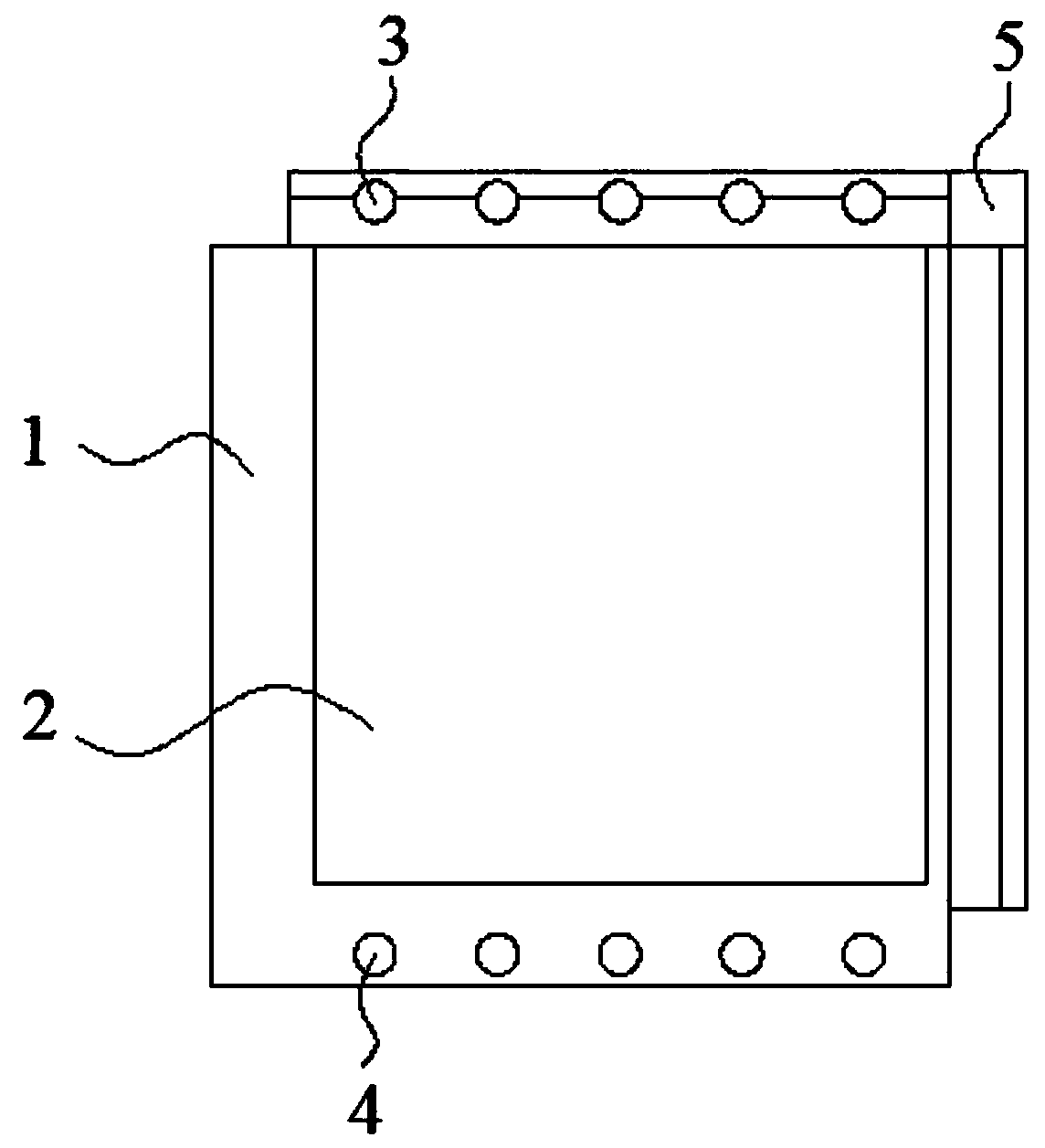
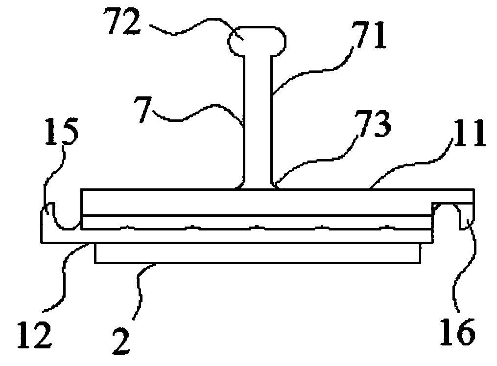
[0030] Such as Figure 1-7 As shown, the revetment concrete block includes a base plate 1, the base plate rear surface 12 of the base plate 1 is connected with a wave reducing slope 2, and the wave reducing slope 2 is an arc-shaped structural section with two slopes, the slope decreases from top to bottom, facing the wave reducing slope 2. Take the place with a large slope as the upward direction, and the clockwise directions are respectively up, right, down, and left; the front surface 11 of the base plate 1 is connected with buried piles 7, and the buried piles 7 are buried in the sandstone layer or soil layer of the embankment as a whole Middle; the upper, lower, left and right sides of the substrate 1 are respectively connected with upper splicing section 13, lower splicing section 14, left splicing section 15 and right splicing section 16; Hole 4. When the water flow rushes to the embankment, the wave reducing slope 2 can straighten the water flow in advance, reduce the ...

Embodiment 2

[0041] Such as Figure 8-11 As shown, the basic structure of the bank revetment concrete block in this embodiment is the same as that of Embodiment 1, the difference is that some bank revetment concrete blocks of different forms are illustrated. Figure 8 and Figure 10 As shown, the shape of the base 1 is a straight quadrangle and a straight octagon respectively, and the relevant projections of the wave reducing slope 2 change with the base 1 into a quadrangle and an octagon respectively, and the structure can be selected according to the laying requirements. Figure 8 and Figure 9 As shown, the buried pile 7 is arranged in a cross shape, and the structure of the buried pile 7 including the rib 71 or the convex step 72 is changed, and the part of the structure near the rib 71 near the convex step 72 is reduced without affecting the structural strength, which is conducive to weight reduction. , or further increase the gripping force between the buried pile 7 and the embankm...

Embodiment 3

[0043] When the bank revetment concrete block of the present invention is actually used, construction workers lay the bank revetment concrete block on the pre-laid compacted silt layer or soil layer embankment, and fill it with sand between the buried pile 7 and the embankment silt layer or soil layer Tamping in the formed cavity increases grip. The upper splicing section 13 and the lower splicing section 14 of adjacent concrete blocks are overlapped in dislocation, and the left splicing section 15 and the right splicing section 16 are aligned and overlapped, so that the wave reducing slope 2 and each splicing section are scattered and distributed, and Each splicing section is a weak point, and double-layer superimposed support is used to make the overall structure more uniform in force and reduce the occurrence of structural damage. Both the upper seepage hole 3 and the lower seepage hole 4 are composed of a number of through holes. After lapping, the upper seepage hole 3 bet...


PUM


Abstract

The invention discloses a concrete block of a revetment and belongs to the field of water conservancy projects. The concrete block comprises a base plate. A wave reducing slope is connected to the back surface of the base plate, the wave reducing slope is composed of one or more arc-shaped structural segments and the gradient of the wave reducing slope is decreased gradually from top to bottom. Aburied pile is connected to the front surface of the base plate, the depth of the buried pile integrally buried into a gravel sand or a soil layer of a bank is greater than a block thickness of the base plate, the circumferential side of the base plate is connected to splicing segments, separately, an upper seepage hole and a lower seepage hole are formed in the directions of the upper and lower splicing segments, separately, and after overlapping, the upper seepage hole is formed right below or obliquely below the lower seepage hole, and gaps are reserved among the corresponding splicing segments. The concrete block of the revetment of a light high strength structure is long in service life and convenient to maintain, can play a smooth flow guiding role, can form relatively high all-roundholding power, and reduces damage caused by wave energy centralization, settlement, expansion and contraction and the like effectively. During construction, it is convenient for a worker to stay, andthe concrete block is convenient to product, transport and fill, so that a revetment structure is protected more favorably.

Description

technical field [0001] The invention belongs to the field of water conservancy engineering, and in particular relates to a bank revetment concrete block. Background technique [0002] The revetment is mainly used to defend against the damage caused by waves and currents in the water area to the slope and land, and to ensure the safety of land personnel and infrastructure. At present, most commonly used revetment structures are formed by connecting concrete blocks, and are designed according to the hydrodynamic characteristics of coasts and river banks. [0003] In order to strengthen the embankment structure and prevent the erosion and loss of sand and soil caused by rapid current impact, surge, rain, etc., the design of revetment structure with better performance is essential. The existing revetment block ignores the integrated structural design that enhances the vertical grip between itself and the embankment sediment layer or soil layer and the mutual support between eac...

Claims


Application Information

Patent Timeline
Patent Type & Authority Applications(China)
IPC IPC(8): E02B3/14
CPCE02B3/14
Inventor 王雪宝陆彩红肖华朱永
Owner 浙江省海洋技术服务中心
Learn More