
Laser processing head based on multiple optical fiber output laser modules

A laser processing head and laser module technology, applied in the laser field, can solve problems such as position drift, reduced laser processing quality, and beam quality degradation

Pending Publication Date: 2020-07-07
方强
View PDF0 Cites 1 Cited by
  • Summary
  • Abstract
  • Description
  • Claims
  • Application Information

AI Technical Summary

Problems solved by technology

[0003] In this kind of laser processing system, there are technically the following problems: First, there is the risk of thermal management: 1. Due to the high power of optical fiber combining, the slight leakage of light in the beam combiner will bring great difficulties to the thermal management of the device, so , the reliability of this beam combiner is poor; 2. The laser optical system is composed of multiple lenses. Due to the poor thermal conductivity of the glass, it can only dissipate heat at the lens frame at the edge of the lens. Under the action of high-power laser, heat will be generated. Lens effect, the position of the working point drifts, and the lens is easy to damage
The deterioration of the beam quality will increase the complexity of the optical system and reduce the quality of laser processing
[0004] In addition, high-power lasers made of fiber beam combiners are expensive. Usually, the unit power laser processing after beam combining is about 2 times the price before beam combining.

Method used


Image

  • Laser processing head based on multiple optical fiber output laser modules
  • Laser processing head based on multiple optical fiber output laser modules
  • Laser processing head based on multiple optical fiber output laser modules

Examples


Embodiment 1

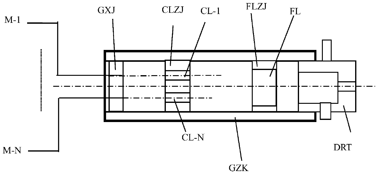
[0034] Embodiment 1: According to the technical scheme of the laser processing head based on multiple optical fiber output laser modules proposed by the present invention, in a certain embodiment of the present invention, it is required to design a laser cutting head with a spot size of 200 microns and a power of 7000 watts. The laser cutting head adopts image 3 The structure shown, its optical system adopts Image 6 The lens structure shown. Among them: the optical axes of the 7 collimating lenses are parallel, the same focal length is 50 mm, and the distance between adjacent lenses is 8 mm, and they are distributed on the same plane; the optical axis of the focusing lens coincides with the optical axis of the collimating lens located in the center, and the focal length is 500 mm; Seven fiber laser modules with an output of 1000 watts are used, the core diameter of the output fiber is 20 microns, and the numerical aperture is 0.06. The output end face of each output fiber i...

Embodiment 2

[0036] Embodiment 2: According to the technical scheme of the laser processing head based on multiple optical fiber output laser modules proposed by the present invention, in a certain embodiment of the present invention, it is required to design a spot with high center power and small edge power, and high power in the center area Laser cutting head with a size of 200 microns, an edge spot size of 400 microns, and a power of 7000 watts. The advantage of this cutting spot is that it can preheat the cutting area and greatly reduce the reflectivity of the material. It is suitable for cutting high reflectivity materials such as copper and aluminum. The laser cutting head adopts image 3 The structure shown, its optical system adopts Image 6 The lens structure shown. Among them: the optical axes of 7 collimating lenses are parallel, the focal length of 6 lenses is 50 mm, the focal length of one lens is 25 mm, and the distance between adjacent lenses is 8 mm, and they are distrib...

Embodiment 3

[0038] Embodiment 3: According to the technical scheme of the laser processing head based on multiple optical fiber output laser modules proposed by the present invention, in a certain embodiment of the present invention, it is required to design a swinging laser welding head with a power of 4000 watts and a light spot of 200 microns. The laser cutting head adopts Figure 4 The structure shown, its optical system adopts Image 6 The lens structure shown. Among them: the optical axes of the 7 collimating lenses are parallel, the same focal length is 50 mm, and the distance between adjacent lenses is 8 mm, and they are distributed on the same plane; the optical axis of the focusing lens coincides with the optical axis of the collimating lens located in the center, and the focal length is 500 mm; One fiber laser module with an output of 1000 watts and six fiber laser modules with an output power of 500 watts are used. The core diameter of the output fiber is 20 microns and the n...


PUM

PropertyMeasurementUnit
Diameteraaaaaaaaaa

Abstract

The invention discloses a laser processing head based on multiple optical fiber output laser modules. The laser processing head comprises the optical fiber output laser modules, a plurality of collimating lenses corresponding to the optical fiber output laser modules one to one, a focusing lens, an optical fiber support, a collimating lens support, a focusing lens support and a tubular shell. Theoutput ends of output optical fibers of the optical fiber output laser modules are fixed to the optical fiber support. The collimating lens comprises at least one lens fixed to the collimating lens support. The focusing lens comprises at least one lens fixed to the focusing lens support. The optical fiber support is fixed in the tubular shell and is close to one end, and the output end faces of the optical fibers face the other end of the tubular shell. A high-power optical fiber beam combiner does not need to be used, the size of the collimating lens is greatly reduced, the cooling effect isimproved, and the thermal lens effect is reduced; and the heat dissipation capability of the focusing lens is greatly improved, the thermal lens effect is reduced, and the processing beam quality is improved.

Description

technical field [0001] The invention belongs to the field of laser technology, and relates to a laser processing head, in particular to a laser processing head based on a plurality of optical fiber output laser modules, which can be widely used in the laser industry. Background technique [0002] At present, in high-power laser processing, when the optical power output by a single fiber output laser cannot meet the requirements, the system configuration method is to combine the light output by multiple optical fiber output laser modules into one optical fiber through a fiber combiner. Then the light output by the fiber combiner is shaped and imaged to the processing surface by the optical system. The composition of this system is: multiple low-power laser modules + beam combiner + laser optical system. At present, due to the convenience and flexibility of the fiber output laser module, the fiber output laser module is the mainstream product model, which can be a fiber-coupl...

Claims


Application Information

Patent Timeline
IPC IPC(8): B23K26/06B23K26/064B23K26/21B23K26/38
CPCB23K26/0604B23K26/064B23K26/0648B23K26/21B23K26/38
Inventor 方强方笑尘
Owner 方强
Learn More