A fixed bed upflow reactor and applications thereof

A reactor and fixed bed technology, applied in the field of upflow reactors, can solve the problems of affecting the start-up period, uneven distribution of fluid gas, and affecting fluid distribution, etc.

Active Publication Date: 2020-07-07
CHINA PETROLEUM & CHEM CORP +1
View PDF10 Cites 1 Cited by
  • Summary
  • Abstract
  • Description
  • Claims
  • Application Information

AI Technical Summary

Problems solved by technology

Since the catalyst particles cannot pass through the small bed support gap, these particles are likely to block the distributor or bed support, resulting in uneven distribution of fluid, especially gas, which affects the distribution of fluid in the reactor and affects the reaction process. adversely affect
At the same time, it will also be accompanied by the wear and pulverization of the catalyst particles, resulting in a large amount of catalyst dust. These dusts move upward with the reaction materials, and clogging occurs on the surface of the screen or grid, resulting in a rapid increase in the pressure drop of the bed, affecting response start cycle

Method used


Image

  • A fixed bed upflow reactor and applications thereof
  • A fixed bed upflow reactor and applications thereof
  • A fixed bed upflow reactor and applications thereof

Examples


Embodiment 1

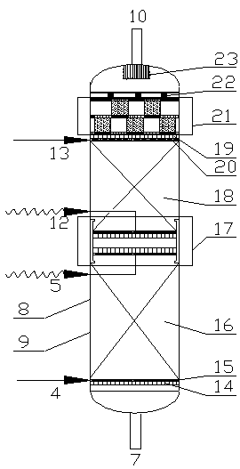
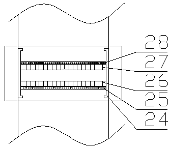
[0050] Using the upflow reactor described in the present invention, part of the raw oil and hydrogen are mixed with a conventional static mixer (model SV2.3 / 25-6.4-500), and then the mixture is used as the reactor feed from the bottom Introduced into an upflow reactor (the diameter of the reactor is DN100), the second and third reaction materials enter from the feed inlets at the bottom and top of the lower catalyst bed respectively; while the first and second circulating materials enter from the upper The feed inlet at the bottom and top of the catalyst bed enters; along the material flow direction in the reactor, there are supporting grids, the first catalyst bed 600mm, the sliding grid layer 200mm, the second catalyst bed 600mm, and the catalyst dust filter layer 200mm ; Wherein, the liquid phase feed that the reaction material inlet, the second reaction material inlet, the third reaction material inlet enters the reactor accounts for 66wt%, 17wt%, 17wt% of the total liquid ...

Embodiment 2

[0052] Using the upflow reactor of the present invention, the raw material oil and hydrogen are mixed with a conventional static mixer (model SV2.3 / 25-6.4-500), and then the mixture is introduced from the bottom as the reactor feed Upflow reactor (reactor diameter is DN100), the second reaction material and the third reaction material enter from the feed inlet at the bottom and top of the lower catalyst bed respectively; while the first circulating material and the second circulating material enter from the upper catalyst bed The feed inlets at the bottom and top of the bed enter; along the material flow direction in the reactor, there are support grids, first catalyst bed 800mm, sliding grid layer 200mm, second catalyst bed 800mm, catalyst dust filter layer 200mm, Gland 100mm; Wherein, the liquid phase feed that the reaction material inlet, the second reaction material inlet, the third reaction material inlet enters the reactor accounts for 72wt%, 18wt%, 18wt% of the total liq...


PUM


Abstract

The invention discloses a fixed bed up-flow reactor and application thereof. The reactor comprises a reactor shell, and a supporting grid, a lower catalyst bed layer, a sliding grid layer, an upper catalyst bed layer and a gland grid are arranged in the reactor shell in the material flowing direction; a reaction material inlet is formed in the bottom of the reactor shell, a reaction material outlet is formed in the top of the reactor shell, and the sliding grid layer comprises an upper sliding grid and a lower sliding grid; the reactor can also be provided with a catalyst dust filtering layerand a gland. The fixed bed up-flow reactor can effectively control the expansion and contraction degree of the catalyst bed layer, prevent the catalyst from causing particle abrasion in the floating process, and reduce the generation of dust while protecting the catalyst.

Description

technical field [0001] The invention belongs to the field of petrochemical equipment, and relates to an upflow reactor and its application. Background technique [0002] In the field of petrochemical industry, hydrogenation process is an important technical means for processing distillate oil and secondary processed oil. Through hydrogenation, impurities such as sulfur, nitrogen, metals, colloids, and residual carbon in oil products can be effectively removed. Removal and hydrogenation of unsaturated hydrocarbons to saturated hydrocarbons. According to the type of reactor, the hydrogenation process can be divided into fixed bed hydrogenation process, suspension bed hydrogenation process and ebullated bed hydrogenation process, among which the fixed bed hydrogenation process is the most widely used. [0003] According to the feeding method of the fixed bed reactor, it can be divided into two types: upflow type, that is, bottom feed and downflow type, that is, top feed fixed ...

Claims


Application Information

Patent Timeline
Patent Type & Authority Applications(China)
IPC IPC(8): B01J8/04C10G49/00
CPCB01J8/0446B01J8/0492B01J2208/00884B01J2208/00911C10G49/00C10G2300/4006C10G2300/4012
Inventor 周嘉文杨秀娜阮宗琳王昊晨姜阳崔国英关明华
Owner CHINA PETROLEUM & CHEM CORP
Why Eureka
Try Eureka