Automated analyzer and automated analyzer control method

一种自动分析装置、控制方法的技术,应用在分析材料、测量装置、通过光学手段进行材料分析等方向,能够解决脱离调整范围等问题

Active Publication Date: 2020-07-03
HITACHI HIGH-TECH CORP
View PDF16 Cites 2 Cited by
  • Summary
  • Abstract
  • Description
  • Claims
  • Application Information

AI Technical Summary

Problems solved by technology

However, in such a method of adjusting the high voltage value, there is a risk of going out of the adjustment range in the circuit that adjusts the high voltage value

Method used


Image

  • Automated analyzer and automated analyzer control method
  • Automated analyzer and automated analyzer control method
  • Automated analyzer and automated analyzer control method

Examples


no. 1 approach

[0029] First, refer to figure 1 The automatic analyzer of the first embodiment of the present invention will be described.

[0030] In this first embodiment, the following automatic analyzer will be described as an example, that is, a photomultiplier tube is used as a detector, and a chemiluminescence method using an acridinium ester as a luminescent label is used in the detection part, but the acridinium ester is only is an example, not limited to.

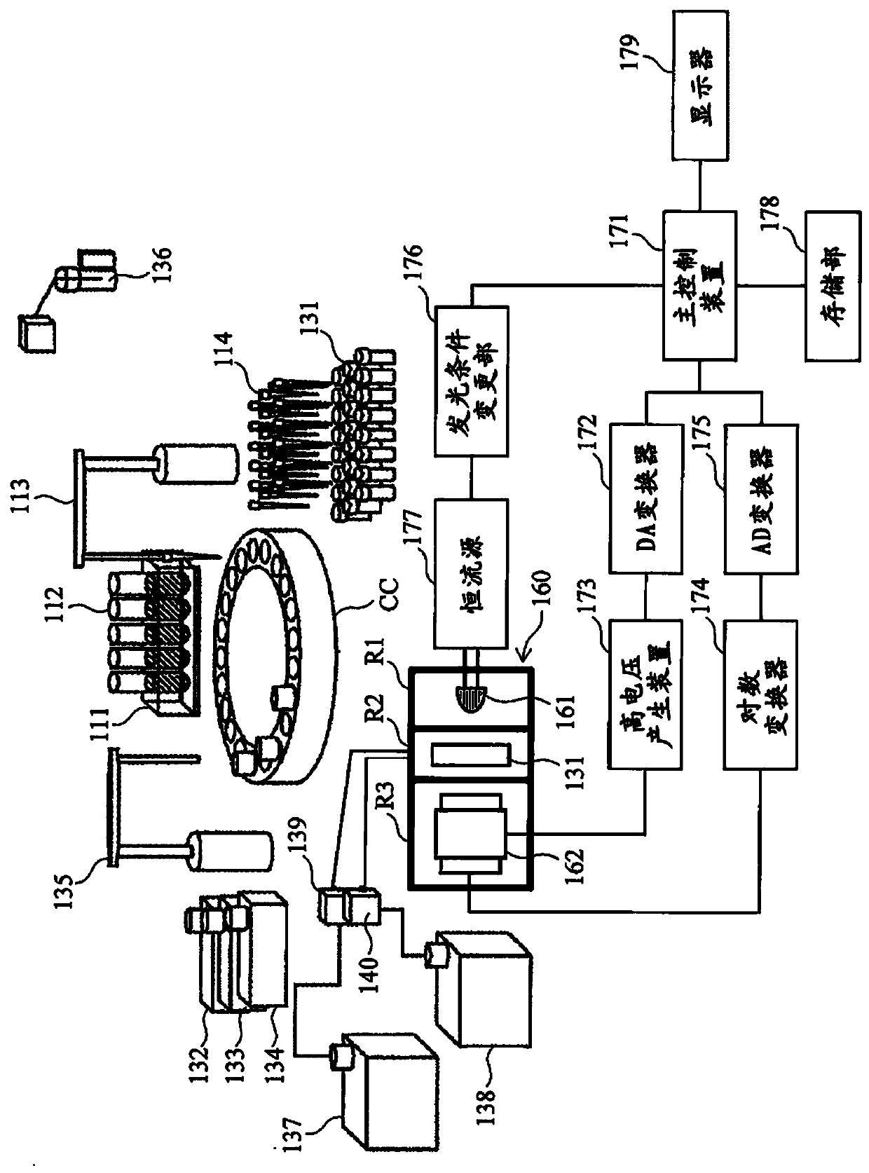
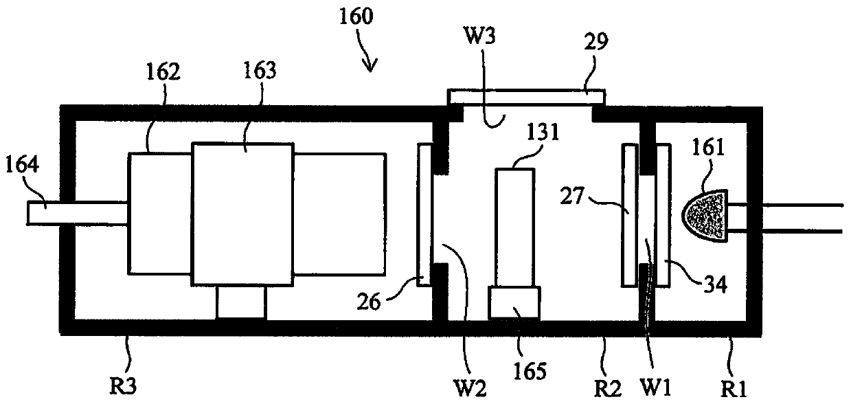
[0031] figure 1 It is a schematic diagram showing the overall configuration of the automatic analyzer of the first embodiment. This apparatus includes a container rack 111 , and is configured such that a test material container 112 can be mounted on the container rack 111 . In addition, this device includes a sampling mechanism 113 that sucks the test material in the test material container 112 through the sampling sheet 114 . The container racks 111 are sequentially transported by a transport mechanism not shown to a positio...

no. 2 approach

[0086] Next, refer to Image 6 and Figure 7 The automatic analyzer of the second embodiment will be described. The appearance of the structure of the device is the same as that of the first embodiment ( figure 1 ) are the same, so repeated explanations are omitted. However, the operation of controlling the sensitivity of the photomultiplier tube 162 in the second embodiment is different from that in the first embodiment. Specifically, this second embodiment differs from the first embodiment in that, in addition to controlling the sensitivity of the photomultiplier tube 162 by irradiating control light, it also performs control by correcting an electric signal. Control of the sensitivity of the photomultiplier tube 162.

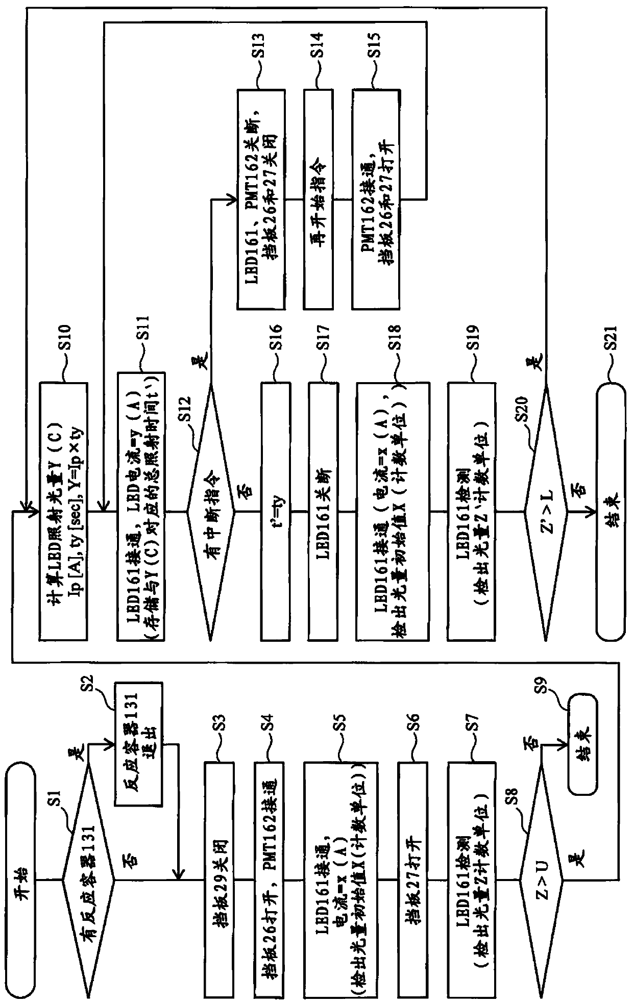
[0087] Image 6 It is a flowchart showing the procedure of inspecting the photomultiplier tube 162 and controlling the sensitivity as necessary in the automatic analyzer of the second embodiment. in addition, Figure 7 It is a conceptual diagram (graph...


PUM


Abstract

The present invention controls the sensitivity of a photomultiplier tube used in an automated analyzer without adjusting a high-voltage value. An automated analyzer according to the present inventionis characterized by comprising: a photomultiplier tube for detecting light from a reaction vessel, an assessment unit for assessing the output signal of the photomultiplier tube when the photomultiplier tube is irradiated with first light, and a control unit for irradiating second light onto the photomultiplier tube in accordance with the assessment results of the assessment unit so as to lower the sensitivity of the photomultiplier tube.

Description

technical field [0001] The present invention relates to an automatic analyzer for analyzing a sample from a living body and a control method for the automatic analyzer. Background technique [0002] Clinically, the concentration of chemical substances such as proteins, lipids, sugars, ions, and various components that constitute them are quantitatively measured in blood, urine and other body fluid components. An apparatus for automating steps necessary for this measurement (such as quantitative collection of a sample sample, mixing with a reagent, judgment of a reaction result, measurement of a change in a substance contained in a reagent, etc.) is called an automatic analyzer. [0003] In such an automatic analyzer, it is required to detect weak light emitted from a luminescent label or the like, and a so-called photomultiplier tube is used as a photodetector. A photomultiplier tube is a vacuum tube that receives light inside the vacuum tube and applies a high voltage of a...

Claims


Application Information

Patent Timeline
Patent Type & Authority Applications(China)
IPC IPC(8): G01N35/00
CPCG01N2035/0444G01N35/00623G01N21/274G01J1/0295G01J1/0228G01J1/0418G01J1/044G01J1/08G01J2001/086G01J2001/4453G01J2001/444G01J2001/4406G01J1/42G01N21/76G01N2201/062G01N2201/067
Inventor 信木俊一郎滨崎孝伸坂诘卓山下善宽田上英嗣高仓树
Owner HITACHI HIGH-TECH CORP
Why Eureka
Try Eureka