
Multichannel light detection apparatus

A light detection device and multi-channel technology, applied in the field of light detection, can solve the problems of high bias power requirements, high cost, inconvenient use, etc.

Inactive Publication Date: 2017-03-22
INST OF AUTOMATION CHINESE ACAD OF SCI
View PDF16 Cites 1 Cited by
  • Summary
  • Abstract
  • Description
  • Claims
  • Application Information

AI Technical Summary

Problems solved by technology

Because the requirements for this type of bias power supply are relatively high and expensive, and the existing photodetectors are all single-channel light detection devices with a bias power supply corresponding to a photodiode sensor, so when there are multiple optical signal detection requirements Only a plurality of such single-channel optical detection devices can be combined into a multi-channel optical detection device, which is inconvenient to use and very expensive

Method used


Image

  • Multichannel light detection apparatus
  • Multichannel light detection apparatus
  • Multichannel light detection apparatus

Examples


Embodiment Construction

[0023] Preferred embodiments of the present invention are described below with reference to the accompanying drawings. Those skilled in the art should understand that these embodiments are only used to explain the technical principles of the present invention, and are not intended to limit the protection scope of the present invention.

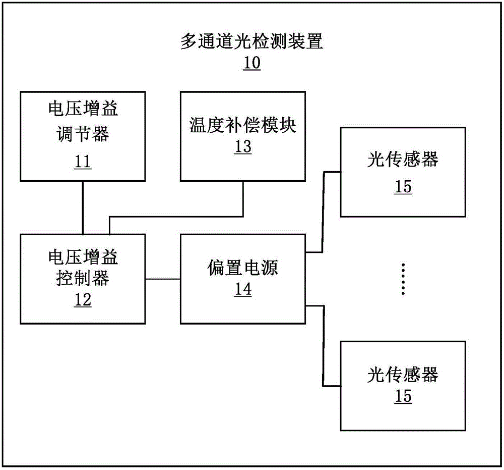
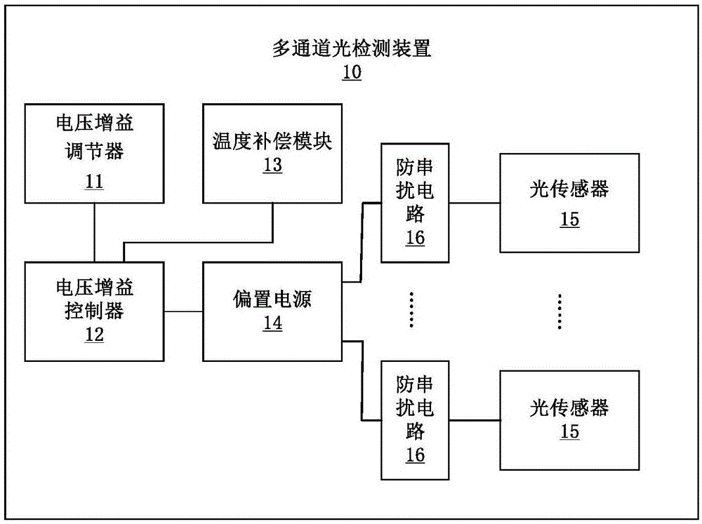
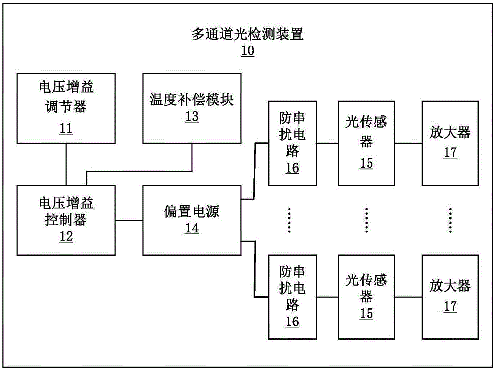
[0024] An embodiment of the present invention provides a multi-channel light detection device. Such as figure 1 As shown, the device 10 may include: a voltage gain regulator 11 , a voltage gain controller 12 , a temperature compensation module 13 , a bias power supply 14 and a plurality of light sensors 15 . Wherein, the voltage gain regulator 11 is used for generating a voltage gain adjustment signal. The voltage gain controller 12 is used to receive the voltage gain adjustment signal transmitted by the voltage gain regulator 11 and the first electrical signal transmitted by the temperature compensation module 13 , superpose the two, and ou...


PUM


Abstract

The invention relates to a multichannel light detection apparatus. A voltage gain regulator is used for generating a voltage gain adjusting signal. A voltage gain controller is used for receiving the voltage gain adjusting signal and a first electrical signal transmitted by a temperature compensating module, superposing the two signals and outputting a voltage gain control signal to a bias power supply. The temperature compensating module is used for collecting operating temperatures of a plurality of light sensors in real time, converting the operating temperatures into the first electrical signal and feeding the first electrical signal back to the voltage gain controller. One bias power supply is used for receiving the voltage gain control signal and generating a bias voltage according to the size of the voltage gain control signal. The plurality of light sensors are used for receiving bias voltages so as to control sensitivities of the plurality of light sensors and are used for receiving optical signals, converting the optical signals into second electric signals and outputting. Therefore, one bias power supply can be used to provide the bias voltages needed by the plurality of light sensors and detection of multichannel light signals is realized.

Description

technical field [0001] The invention relates to the technical field of light detection, in particular to a multi-channel light detection device. Background technique [0002] In practical applications, signal detection often needs to detect multiple signals at the same time, which requires multiple signal detection channels at the same time. In optical signal detection, especially weak optical signal detection, in order to obtain a relatively high detection sensitivity, the photodiode as an optical sensor needs to work in a bias voltage mode, that is, a bias power supply is required to provide a bias voltage for the photodiode. Because the requirements for this type of bias power supply are relatively high and expensive, and the existing photodetectors are all single-channel light detection devices with a bias power supply corresponding to a photodiode sensor, so when there are multiple optical signal detection requirements Only a plurality of such single-channel light dete...

Claims


Application Information

Patent Timeline
Patent Type & Authority Applications(China)
IPC IPC(8): G01J1/44
CPCG01J1/44
Inventor 蒋田仔张鑫左年明徐文廷
Owner INST OF AUTOMATION CHINESE ACAD OF SCI
Learn More