A connector and plug
A plug and plug housing technology, applied in the direction of connection, connecting device parts, contact parts, etc., can solve the problems of frequent rotation, reduce the efficiency of connector assembly, frequently rotate the connecting nut, etc., to improve assembly efficiency and shorten the time. Assembly time, the effect of easy insertion and matching
- Summary
- Abstract
- Description
- Claims
- Application Information
AI Technical Summary
Problems solved by technology
Method used
Image

Examples
specific Embodiment 1
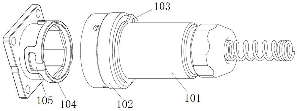
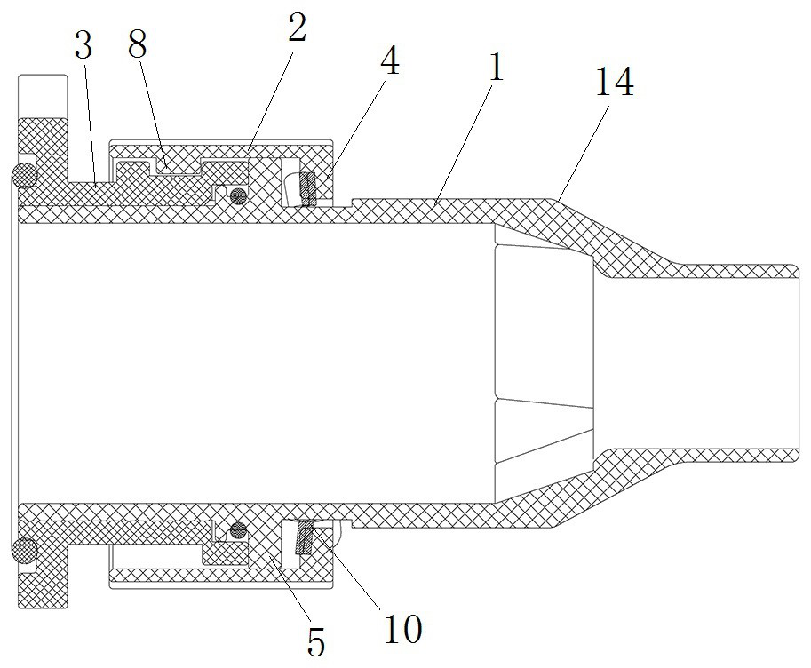
[0034] Such as figure 2 As shown, the connector includes a plug 14 and a receptacle 3 that are mated with each other. The plug 14 includes a plug housing 1 and a connecting nut 2. The plug housing 1 has a plugging section at the front end, and the connecting nut 2 is from the rear to the front. Set on the plug-in section of the plug housing 1, after the plug housing 1 and the socket 3 are inserted in place, the connecting nut 2 is locked and connected with the socket 3 through the curved groove structure of the nail, so as to prevent the plug 14 from loosening from the socket 3 take off.
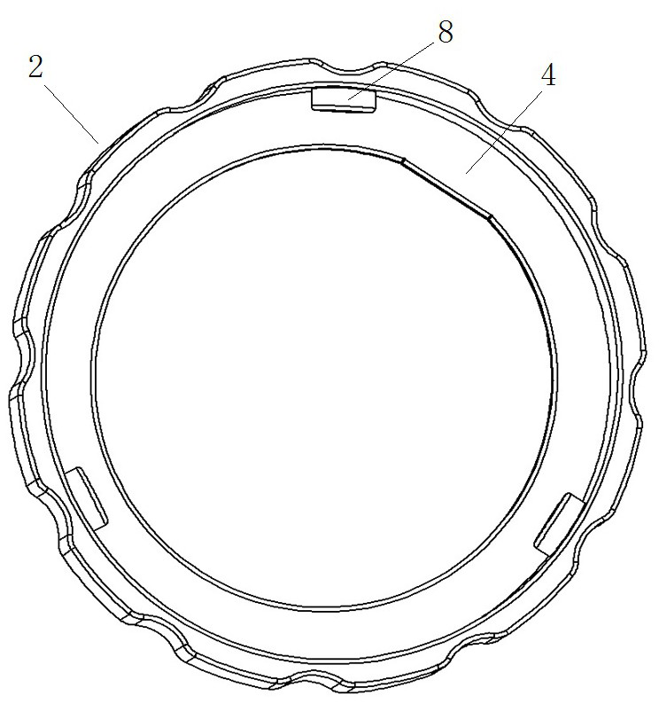
[0035] Such as image 3 and Figure 5 As shown, the inner peripheral surface of the connecting nut 2 is provided with a protrusion 8 integrally formed with the connecting nut 2 and extending radially inward toward the connecting nut 2, and the socket 3 is provided with a protrusion 8 to fit The curved groove 9 is an L-shaped groove, and the front end of the curved groove 9 extends along ...
specific Embodiment 2
[0047] It differs from Embodiment 1 in that: the limit position is the position where the connecting nut rotates clockwise relative to the plug housing to the position where the connecting nut and the plug housing stop and fit. After the plug housing and the socket are inserted in place, rotate the entire plug to align the plug housing and the socket in the circumferential direction, then rotate the connecting nut relative to the plug housing, and turn the connecting nut clockwise to the limit relative to the plug housing position, the protrusion on the connecting nut is aligned with the notch of the curved groove on the socket in the circumferential direction, and the entire plug is pushed forward to realize the insertion of the plug shell and the socket and the connecting nut and the socket. After the connecting nut and the socket are plugged in place in the axial direction, the connecting nut is rotated counterclockwise, so that the protrusion on the connecting nut slides in...
specific Embodiment 3
[0049] It differs from Example 1 in that:
[0050] The curved groove on the socket is a T-shaped groove, and the front section of the curved groove is arranged along the axial extension of the socket. There are two limit positions, respectively, the connecting nut rotates clockwise relative to the plug housing to the positive limit position where the connecting nut and the plug housing stop and cooperate, and the connecting nut rotates counterclockwise relative to the plug housing to the connecting nut Reverse limit position for stop fit with plug housing.
[0051] Between the two limit positions, the rotation angle range of the connecting nut relative to the plug housing is 120°, and there are three protrusions on the connecting nut and curved grooves on the socket, which can satisfy the positive limit of the connecting nut position or reverse limit position, and when the plug housing and the socket are aligned in the circumferential direction, the protrusion on the connecti...
PUM
 Abstract
Description
Claims
Application Information
 - R&D
- Intellectual Property
- Life Sciences
- Materials
- Tech Scout
- Unparalleled Data Quality
- Higher Quality Content
- 60% Fewer Hallucinations
Browse by: Latest US Patents, China's latest patents, Technical Efficacy Thesaurus, Application Domain, Technology Topic, Popular Technical Reports.
© 2025 PatSnap. All rights reserved.Legal|Privacy policy|Modern Slavery Act Transparency Statement|Sitemap|About US| Contact US: help@patsnap.com