
Energy simulation system and device

A technology for simulating systems and energy, applied in the electrical field, can solve problems such as increased calculation, limited boosting capacity, and large computing resources

Inactive Publication Date: 2020-07-03
CHINA UNIV OF MINING & TECH
View PDF4 Cites 0 Cited by
  • Summary
  • Abstract
  • Description
  • Claims
  • Application Information

AI Technical Summary

Problems solved by technology

[0003] The main circuit of the existing photovoltaic array simulator mainly uses non-isolated circuits such as BUCK circuit and two-quadrant chopper circuit. The power is small and the boosting capacity is limited. When the main circuit fails, because there is no isolation transformer, the back-end equipment will be damaged. , such as damage to the photovoltaic inverter
[0004] The existing energy simulation system uses a calculation method for the simulation of the photovoltaic characteristic curve. The calculation method is to calculate the current value in real time according to the input voltage through the equivalent relational expression of the photovoltaic curve. Since the equivalent relational expression of the photovoltaic curve cannot be directly Calculation and generation, and the commonly used Newton iteration method requires a large amount of computing resources, resulting in a decrease in system response performance, especially when simulating the shadow of a photovoltaic array, the equivalent relationship of the photovoltaic curve changes alternately, and the amount of calculation increases exponentially , the existing calculation method simulation can not meet the real-time requirements

Method used


Image

  • Energy simulation system and device
  • Energy simulation system and device
  • Energy simulation system and device

Examples


Embodiment Construction

[0036] Example embodiments will now be described more fully with reference to the accompanying drawings. Example embodiments may, however, be embodied in many forms and should not be construed as limited to the embodiments set forth herein; rather, these embodiments are provided so that this disclosure will be thorough and complete, and will fully convey the concept of example embodiments to those skilled in the art. The same reference numerals denote the same or similar parts in the drawings, and thus their repeated descriptions will be omitted.

[0037] Furthermore, the described features, structures, or characteristics may be combined in any suitable manner in one or more embodiments. In the following description, numerous specific details are provided in order to give a thorough understanding of embodiments of the present disclosure. However, those skilled in the art will appreciate that the technical solutions of the present disclosure may be practiced without one or mo...


PUM


Abstract

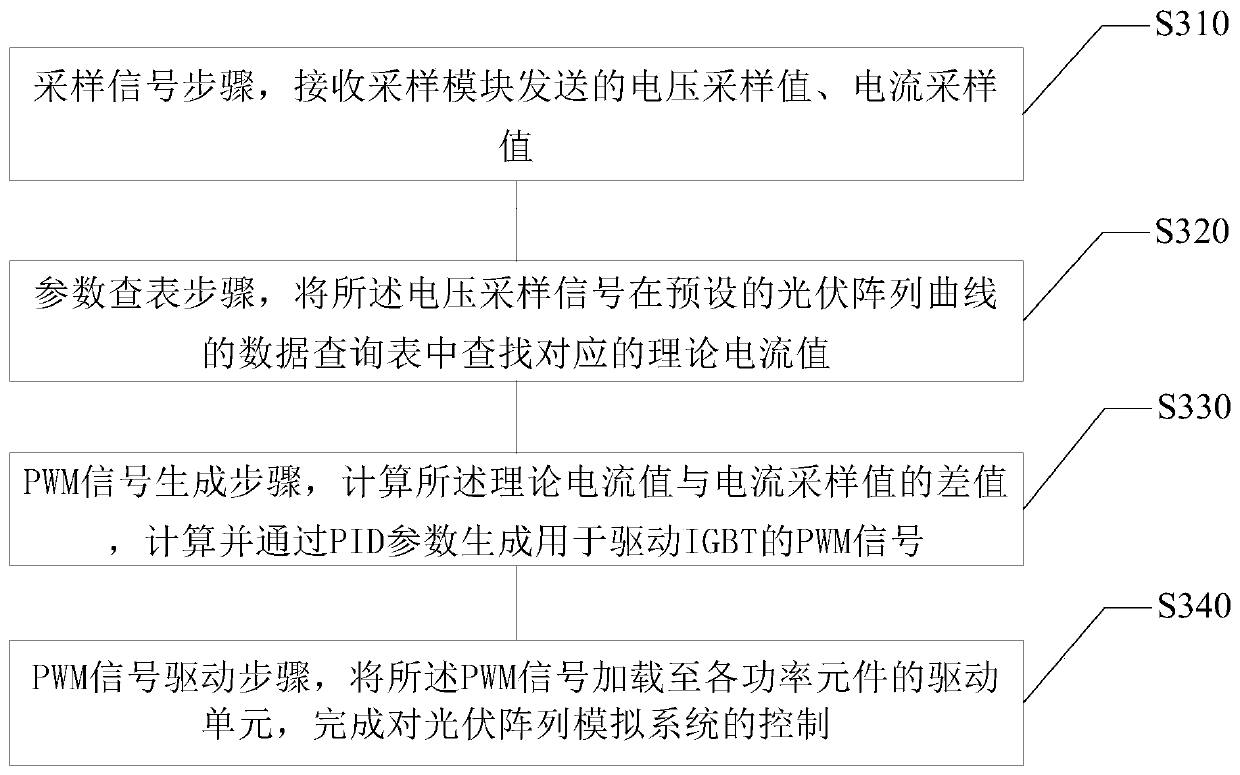
The invention relates to an energy simulation system and method and electronic equipment. The system comprises a rectification module, an isolation module, an inverter, a sampling module, a control module, a driving module and a power supply module, the rectification module is connected with the input end of the inverter through the isolation module. Wherein the input end of the sampling module isconnected with the output end of the isolation module, the output end of the sampling module is connected with the input end of the control module, the output end of the control module is connected with the input end of the driving module, the output end of the driving module is connected with the isolation module, and the power module is connected with the driving module and the control module.According to the invention, the isolated passive clamp phase-shifting full-bridge circuit is used as a main circuit, so that high-power operation and a wide voltage regulation range can be realized, electrical isolation protection of the inverter is realized, and the safety performance of the system is enhanced. And a table look-up mode is adopted as a photovoltaic characteristic curve simulationmode, so that the quick responsiveness of simulating the photovoltaic characteristic curve is improved, and a large amount of storage space does not need to be occupied.

Description

technical field [0001] The present disclosure relates to the electrical field, and in particular, relates to an energy simulation system, method and electronic equipment. Background technique [0002] Solar photovoltaic grid-connected power generation has become the main method and research hotspot of solar energy utilization due to its advantages of renewable, low pollution, and easy transmission. , if a physical solar photovoltaic array is used as input, its light intensity, temperature and other factors lead to a long simulation debugging period, and many situations are not easy to simulate and other problems limit the debugging of photovoltaic grid-connected inverters. Since the energy simulation system can simulate the output of the solar characteristic curve under any temperature and light intensity in a short period of time, its development solves the above problems, greatly shortens the development cycle of photovoltaic grid-connected inverters and reduces its cost. ...

Claims


Application Information

Patent Timeline
IPC IPC(8): G06F30/20
Inventor 朱铭达梁睿黄宏旭任浩栋陆梦恬
Owner CHINA UNIV OF MINING & TECH
Learn More