Phase imaging method based on thin scattering medium
An imaging method and medium technology, applied in image detector methods and image signal processing, phase influence characteristic measurement, material analysis by optical means, etc. Application scenarios and other issues, to achieve the effects of good robustness, improved phase estimation accuracy, and high reconstruction quality
Pending Publication Date: 2020-07-03
SOUTHEAST UNIV
View PDF4 Cites 11 Cited by
- Summary
- Abstract
- Description
- Claims
- Application Information
AI Technical Summary
Problems solved by technology
However, due to the iterative calculation process of most phase recovery algorithms, in addition to the strict calibration of the experimental system, it is also necessary to obtain the prior knowledge of the target or the measurement of multiple observation pla
Method used
View moreImage
Smart ImageViewing Examples
Examples
 PUM
 Abstract
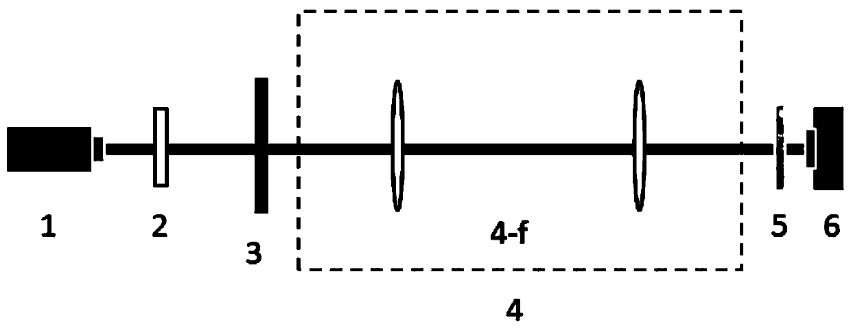
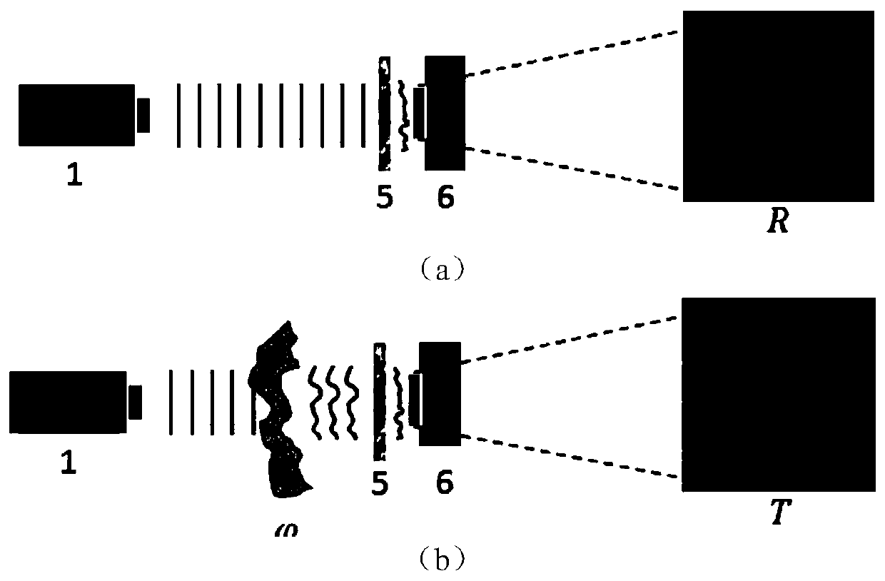
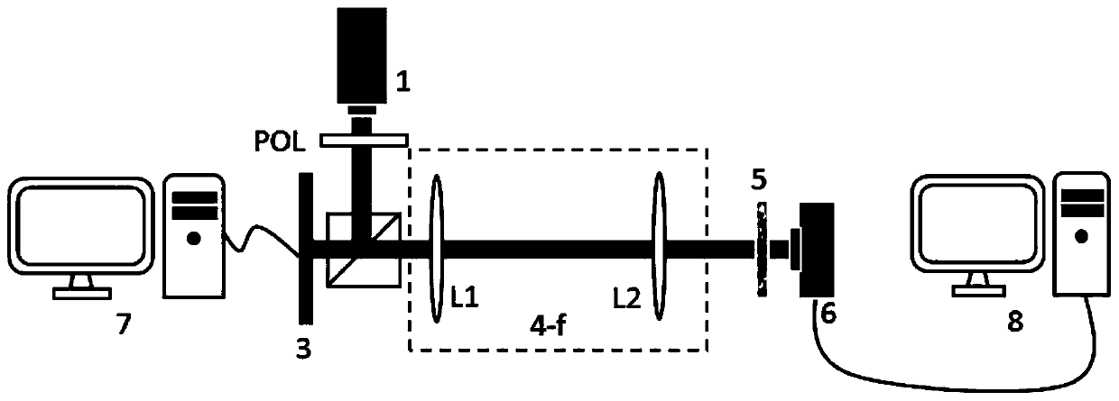
The invention provides a phase imaging method based on a thin scattering medium. The method comprises: placing a thin scattering medium in front of a digital image sensor, adjusting the distance between a target wavefront and the digital image sensor, matching the pixel size, making incident light to penetrate through the thin scattering medium to form speckles distributed spatially, and using thedigital image sensor for collecting formed speckle patterns; preprocessing the original speckle pattern; building a CNN and training a network by using the acquired and preprocessed picture pair data; extracting wavefront information in a speckle pattern by using a trained CNN network, the input of the network being a processed single-frame speckle pattern, and the output of the network being a phase grey-scale map or an amplitude grey-scale map or a complex amplitude corresponding to the wavefront according to a specific imaging task and a network training data set composed of different components. According to the invention, a single-frame, real-time and no-reference phase extraction method is realized, and the method has high image reconstruction quality and good robustness.
Description
technical field [0001] The invention belongs to the field of optoelectronic technology and relates to a phase imaging method, in particular to a phase imaging method based on a thin scattering medium. Background technique [0002] Phase imaging is mainly used to deal with the phase problem in optical imaging and is one of the components of holographic imaging. Since the existing photoelectric imaging devices or optical imaging systems can only capture the intensity information of the scene, it is quite difficult to reconstruct the complex amplitude (amplitude and phase) directly through the original amplitude recording, so special optical recording methods and algorithms are needed The phase information of the scene and the target is recovered. [0003] Existing complex amplitude recording techniques, such as digital holography, can encode and extract target amplitude and phase information through optical interference. In addition to being widely used in 3D image photograp...
Claims
Login to View More Application Information
Patent Timeline
 IPC IPC(8): G01N21/41G01N21/17
CPCG01N21/41G01N21/1717G01N2021/1725G01N2021/1765G01N2021/4186Y02A90/10
Inventor 周真宇夏军
Owner SOUTHEAST UNIV
- R&D Engineer
- R&D Manager
- IP Professional
- Industry Leading Data Capabilities
- Powerful AI technology
- Patent DNA Extraction
Learn More Browse by: Latest US Patents, China's latest patents, Technical Efficacy Thesaurus, Application Domain, Technology Topic, Popular Technical Reports.
© 2024 PatSnap. All rights reserved.Legal|Privacy policy|Modern Slavery Act Transparency Statement|Sitemap|About US| Contact US: help@patsnap.com


