Highway bridge guardrail maintenance equipment

A technology for road bridges and guardrails, which is applied in road surface cleaning, construction, cleaning methods, etc., can solve the problems of single maintenance and cleaning functions, inconvenient promotion and implementation, and high manufacturing costs, so as to improve cleaning quality, meet sustainable development requirements, and operate convenient effect

Pending Publication Date: 2020-07-03
SHAANXI RAILWAY INST
View PDF1 Cites 4 Cited by
  • Summary
  • Abstract
  • Description
  • Claims
  • Application Information

AI Technical Summary

Problems solved by technology

The equipment has complex structure, high manufacturing cost, no effective reuse of water resources, single maintenance and cleaning functions, and is not easy to promote and implement

Method used


Image

  • Highway bridge guardrail maintenance equipment
  • Highway bridge guardrail maintenance equipment
  • Highway bridge guardrail maintenance equipment

Examples


Embodiment 1

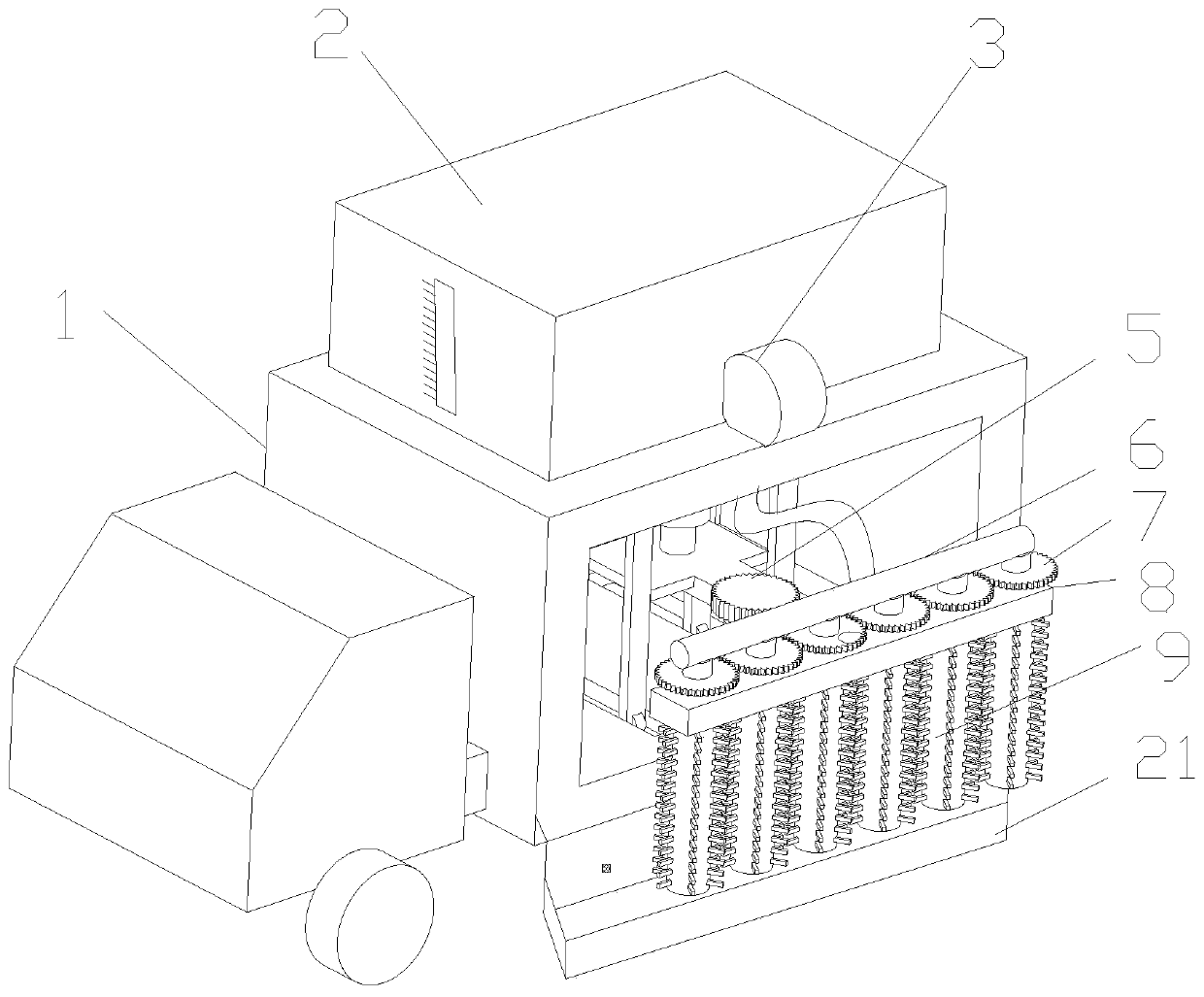
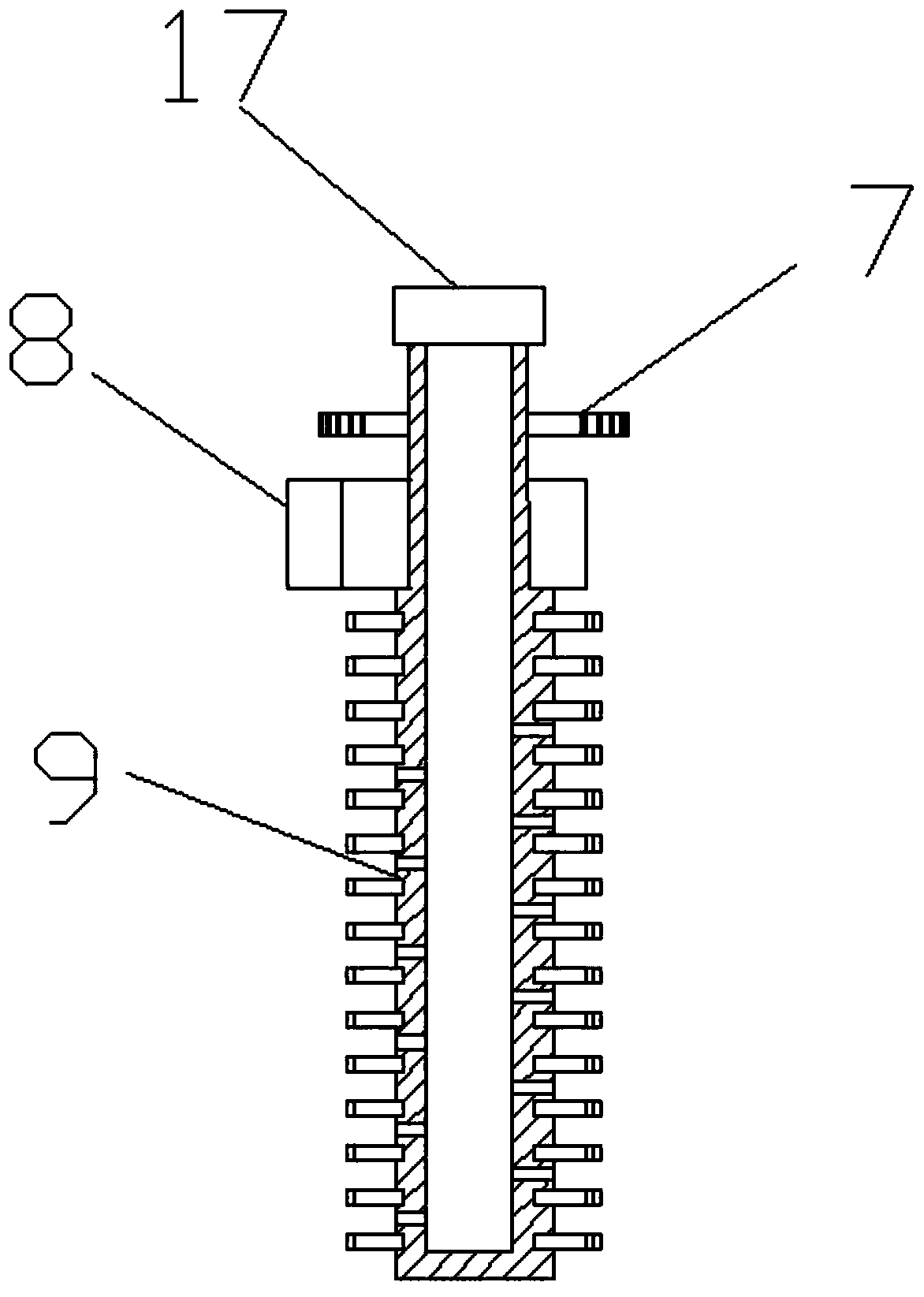
[0022] see Figure 1-4 , figure 1 It is a three-dimensional structural schematic diagram of a highway bridge guardrail maintenance equipment. figure 2 It is a schematic diagram of the front structure of a highway bridge guardrail maintenance equipment. image 3 It is a structural schematic diagram of a brush roller in a road bridge guardrail maintenance equipment. Figure 4 It is a schematic diagram of the use state of a highway bridge guardrail maintenance equipment. In the figure, a highway bridge guardrail maintenance equipment includes a carriage 1 and a brush roller 9 . The interior of the compartment 1 is slidingly provided with a translation frame 11, the inner wall of the compartment 1 is fixedly connected to one end of the first hydraulic rod 10, and the other end of the first hydraulic rod 10 is fixedly connected to the translation frame 11, and this end has a displacement sensor 20 , by monitoring the expansion and contraction of the first hydraulic rod 10, the...

Embodiment 2

[0027] On the basis of Embodiment 1, a water tank 2 is arranged on the compartment 1, and a water pump 3 is fixedly arranged on the compartment 1. The water tank 2 communicates with the water pump 3, and the water pump 3 communicates with the water distribution pipe 6 through a hose. There is a water spray hole, and the water distribution pipe 6 is rotatably connected by the shaft seal 17. Under the action of the water pump 3, the water inside the water tank 2 enters the inside of the brush roller 9 and is sprayed from the water spray hole, thereby facilitating the cleaning of the guardrail. Thereby the cleaning degree of the guardrail is improved. The water tank 2 is provided with an observation window, the setting of the observation window is convenient for observing the state of the water inside the water tank 2, and the observation window is engraved with a scale line, and the setting of the scale line is convenient for quantitatively observing the amount of water. The inb...


PUM


Abstract

The invention discloses highway bridge guardrail maintenance equipment. The equipment comprises a compartment and brush rollers; a translation frame is arranged in the carriage in a sliding manner; adisplacement sensor can monitor large deformation of the guardrail; a second hydraulic rod is fixedly arranged on and connected with a translation frame; the bottom of the second hydraulic rod is fixedly connected with a lifting frame; the lifting frame is arranged in the translation frame in a liftable sliding manner; the outer end of the lifting frame is fixedly connected with a mounting frame;a plurality of brush rollers are rotationally arranged on the mounting frame; the brush rollers are coaxially and fixedly connected with driven gears; every two adjacent driven gears are engaged witheach other; a motor is fixedly installed on the side wall of the mounting frame; an output shaft of the motor is coaxially and fixedly connected with a driving gear, which is mounting with one of thedriven gears; and a square tray is fixed to the bottom of the compartment and used for recycling cleaning water resources. The equipment is simple in structure, complete in function, convenient to operate, high in cleaning quality, capable of recycling water resources and convenient to popularize and implement.

Description

technical field [0001] The invention relates to the technical field of road maintenance equipment, in particular to maintenance equipment for road bridge guardrails. Background technique [0002] Guardrail --- here refers to the industrial "guardrail". Guardrails are mainly used for the protection and protection of personal safety and equipment and facilities in residences, highways, commercial areas, public places and other occasions. Guardrails can be seen everywhere in our lives. Depending on the height of the guardrail, the price per meter of length will also vary. The guardrail is usually made of steel, such as: stainless steel, round steel pipe, square steel pipe or profiled steel plate, iron wire. Surface treatment process: automatic electrostatic powder spraying (that is, plastic spraying) or painting. In recent years, plug-in and assembled guardrails made of aluminum alloy have become more popular. The existing cleaning of bridge guardrails for traffic is mainl...

Claims


Application Information

Patent Timeline
Patent Type & Authority Applications(China)
IPC IPC(8): E01H1/00
CPCE01H1/005
Inventor 李刚高珊珊赵欢都志强李利利
Owner SHAANXI RAILWAY INST
Why Eureka
Try Eureka