
Limiting protection structure for motor hoisting and transportation

A protective structure and motor technology, applied in transportation and packaging, packaging food, assembling machines, etc., can solve problems such as inability to buffer the motor, damage to the internal parts of the motor, and affect the service life of the motor, so as to ensure the protection effect and improve the limit The effect of bit fixed effects

Inactive Publication Date: 2020-07-03
周敏
View PDF24 Cites 0 Cited by
  • Summary
  • Abstract
  • Description
  • Claims
  • Application Information

AI Technical Summary

Problems solved by technology

[0003] In order to solve the above-mentioned technical problems, the present invention provides a position-limiting protection structure for hoisting and transporting motors to solve the problem that the existing similar position-limiting protection structures for motors have poor protection effects on all directions of the motor. When it is dropped or the outside is impacted by external force, the impact force on the outside of the motor cannot be buffered by the limit protection structure. When the impact force is too large, it is easy to cause damage to the internal parts of the motor and affect the service life of the motor.

Method used


Image

  • Limiting protection structure for motor hoisting and transportation
  • Limiting protection structure for motor hoisting and transportation
  • Limiting protection structure for motor hoisting and transportation

Examples


Embodiment

[0030] as attached figure 1 to attach Figure 9 Shown:

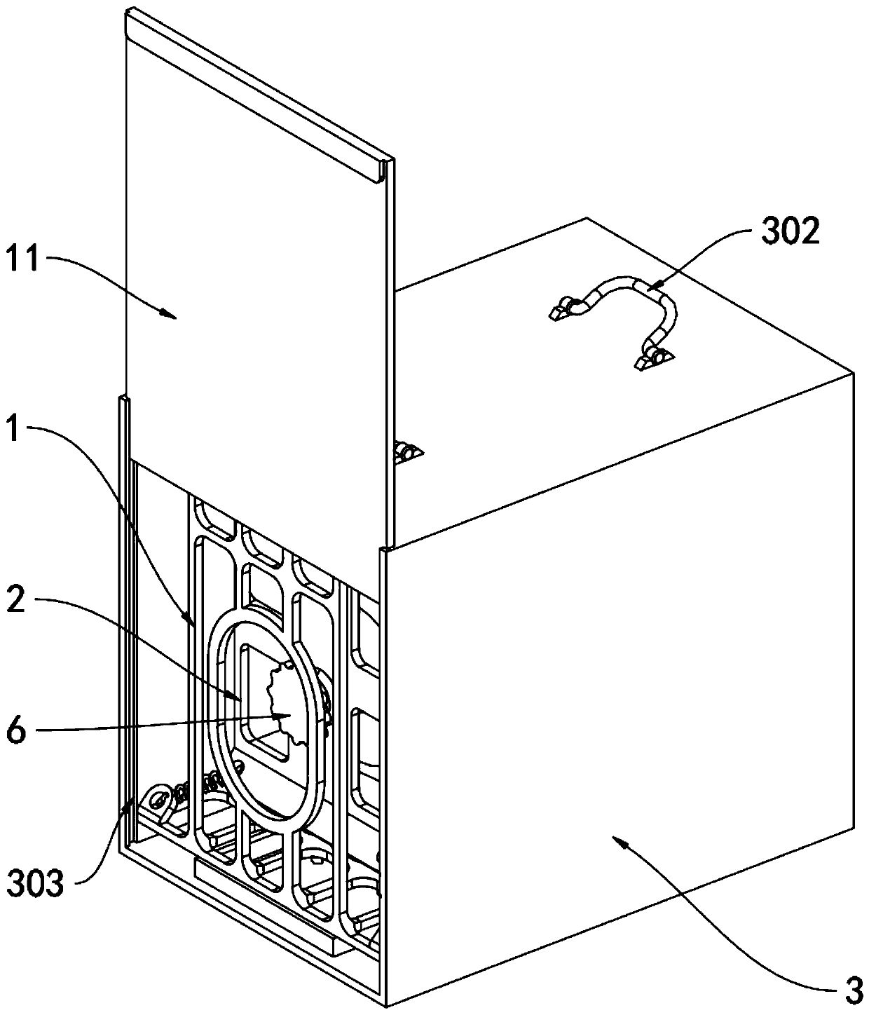
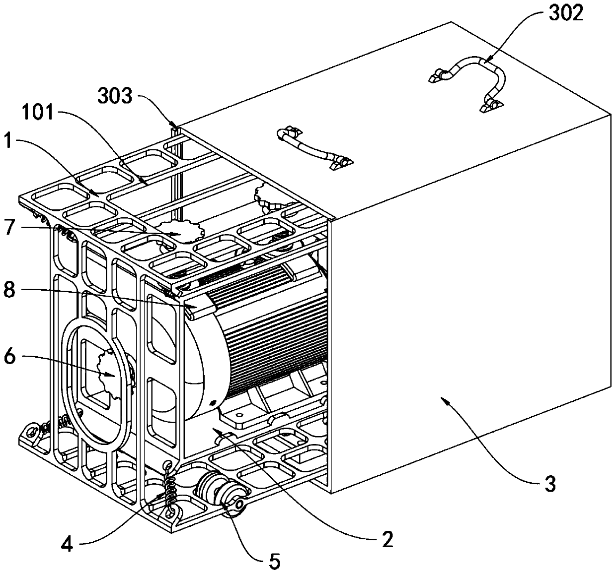
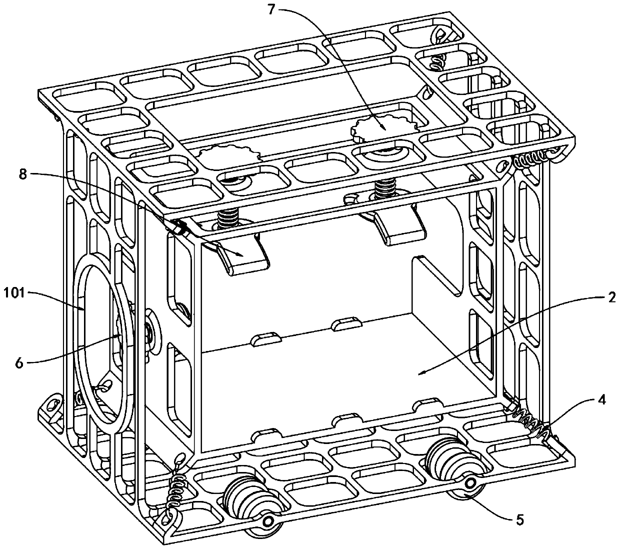
[0031] The invention provides a position-limiting protective structure for hoisting and transporting a motor, which includes an outer protective frame 1, an inner protective frame 2, an outer protective shell 3, a position-limiting bolt 6, a pressing bolt 7, an arc-shaped position-limiting plate 8, a porous moisture-absorbing Plate 9 and outer baffle plate 11; outer cage 1 is a square structure, and the top four ends and bottom four ends of the outer cage 1 are respectively connected with the buffer spring 4; the inner cage 2 is a square structure, and the inner cage 2 is The suspended shape is located inside the outer casing 1; the top of the outer casing 3 is provided with two hoisting handles 302, and the outer casing 1 and the inner casing 2 are both located inside the outer casing 3; there are eight buffer springs 4, divided into There are two sets of upper and lower groups, and the inner cage 2 is connected with ...


PUM


Abstract

The invention provides a limiting protection structure for motor hoisting and transportation, and relates to the technical field of motor hoisting and transportation. The limiting protection structurecomprises an outer protective frame, an inner protective frame and an outer protective shell; the outer protective frame is of a square structure, and the four ends of the top of the outer protectiveframe and the four ends of the bottom of the outer protective frame are correspondingly connected with buffer tension springs; the inner protective frame is of a square structure, and the inner protective frame is located in the outer protective frame in a suspended mode; two hoisting hanging handles are arranged at the top of the outer protective shell, and both the outer protective frame and the inner protective frame are located inside the outer protective shell; eight buffer tension springs are arranged and the eight buffer tension springs are divided into upper and lower groups, and theouter protective frame is connected with the inner protective frame through the buffer tension springs; and limiting bolts are located at the left end of the inner protective frame, and pressing boltsare located at the top of the inner protective frame. According to the limiting protection structure for motor hoisting and transportation, when a motor on the outer side of the outer protective frame is impacted by an external force or falls from a high position, impact force is flexibly buffered by the buffer tension springs connected between the inner protective frame and the outer protectiveframe, the influence of the impact force on the motor in the inner protective frame is reduced, and the motor protection effect is guaranteed.

Description

technical field [0001] The invention belongs to the technical field of motor hoisting and transportation, and more specifically relates to a position-limiting protection structure for motor hoisting and transportation. Background technique [0002] The motor is a device that converts electrical energy into mechanical energy. It uses a energized coil to generate a rotating magnetic field and acts on the rotor to form a magnetoelectric torque. The motor is divided into DC motors and AC motors according to the power supply used. When transporting large and medium-sized motors , due to the heavy volume of the motor, the motor is usually transported by hoisting. In the hoisting of the motor, it is usually necessary to limit and fix the motor to ensure the stability of the motor hoisting operation; the motor limit protection structure can refer to the CN107352182B patent. It mainly includes three pre-buffer mechanisms distributed in an equilateral triangle and a support mechanism ...

Claims


Application Information

Patent Timeline
IPC IPC(8): B65D25/14B65D85/68B65D25/20B65D81/05
CPCB65D25/14B65D25/20B65D81/05B65D85/68
Inventor 周敏
Owner 周敏
Learn More