
Glass kiln denitration system

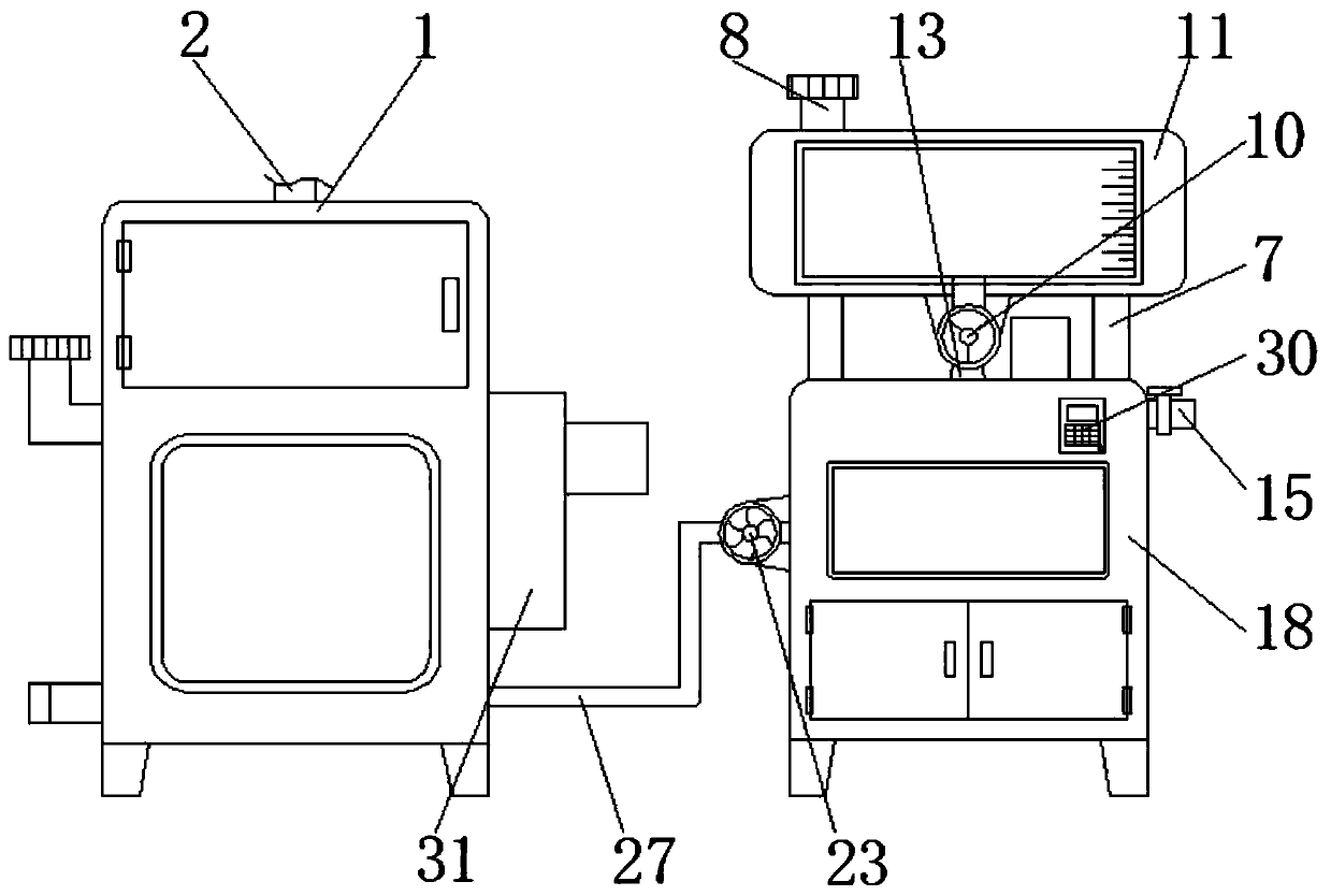
A glass kiln and denitrification technology, applied in fixed tubular conduit components, dispersed particle filtration, lighting and heating equipment, etc., can solve the inconvenience of users, uneven combination of ammonia water and flue gas, and poor heat exchange effect of flue gas Good and other questions

Inactive Publication Date: 2020-07-03
淮北森诺环保科技有限公司
View PDF0 Cites 3 Cited by
  • Summary
  • Abstract
  • Description
  • Claims
  • Application Information

AI Technical Summary

Problems solved by technology

[0004] The purpose of the present invention is to provide a glass kiln denitrification system, which has the advantages of high-efficiency denitrification and good heat exchange effect on flue gas, and solves the problem of the combination of ammonia water and flue gas in the denitrification process of the existing glass kiln denitrification system. The relatively uneven, resulting in low denitrification efficiency, and usually the structure of flue gas heat exchange is relatively simple, which makes the effect of flue gas heat exchange poor, and it is easy to cause some inconvenience to users.

Method used


Image

  • Glass kiln denitration system
  • Glass kiln denitration system
  • Glass kiln denitration system

Examples


Embodiment Construction

[0029] The following will clearly and completely describe the technical solutions in the embodiments of the present invention with reference to the accompanying drawings in the embodiments of the present invention. Obviously, the described embodiments are only some, not all, embodiments of the present invention. Based on the embodiments of the present invention, all other embodiments obtained by persons of ordinary skill in the art without making creative efforts belong to the protection scope of the present invention.

[0030] In the description of the invention, it should be noted that the terms "upper", "lower", "inner", "outer", "front end", "rear end", "both ends", "one end", "another end" etc. The indicated orientation or positional relationship is based on the orientation or positional relationship shown in the drawings, and is only for the convenience of describing the present invention and simplifying the description, rather than indicating or implying that the referre...


PUM


Abstract

The invention discloses a glass kiln denitration system. The glass kiln denitration system comprises a first box body and a second box body. The first box body, an air inlet pipe, a frame body, a belt, a first motor, an annular pipe, a support column, a second liquid inlet valve, an ammonia gas sensor, a water pump, a water tank, a second motor, a rubber hose, a rotating shaft, an exhaust valve, adriving gear, an atomizing nozzle, the second box body, a third filter screen, a drawer, a communicating pipe, a driven gear, a water pump, a belt pulley, a second spiral blade rod, a first spiral blade rod, a snake-shaped heat exchange pipe, a partition plate, a first filter screen, a controller, a shell, active carbon balls, and a second filter screen cooperate with each other to solve the problems that in the denitration process of an existing glass kiln denitration system, ammonia water and flue gas are generally not evenly combined, the denitration efficiency is low, in addition, the flue gas heat exchange structure is generally single, the flue gas heat exchange effect is poor, and the system is inconvenient to use.

Description

technical field [0001] The invention relates to the technical field of glass processing, in particular to a denitrification system for a glass kiln. Background technique [0002] Glass furnace is a kind of melting device that glass manufacturing industry must have. [0003] In the process of glass processing, it is often necessary to use the glass kiln denitrification system to denitrify the flue gas generated by the glass kiln. The existing glass kiln denitrification system usually combines ammonia water and flue gas unevenly during the denitrification process. As a result, the efficiency of denitrification is low, and the structure of flue gas heat exchange is usually relatively simple, which makes the effect of flue gas heat exchange poor, and it is easy to cause certain inconvenience to users. Contents of the invention [0004] The purpose of the present invention is to provide a glass kiln denitrification system, which has the advantages of high-efficiency denitrific...

Claims


Application Information

Patent Timeline
Patent Type & Authority Applications(China)
IPC IPC(8): B01D53/86B01D46/12B01D46/00F28D7/08F28F13/12B01D53/56
CPCB01D46/0036B01D46/12B01D53/8625B01D2251/2062B01D2258/0283F28D7/082F28F13/125
Inventor 张作培
Owner 淮北森诺环保科技有限公司
Learn More