Intelligent cultivation system of sweet potatoes through drip irrigation
An intelligent and sweet potato technology, applied in the field of agricultural irrigation, can solve the problems of wasting manpower, reducing irrigation efficiency, and low level of intelligent irrigation, and achieving the effects of preventing clogging, improving drip irrigation efficiency, and saving manpower
- Summary
- Abstract
- Description
- Claims
- Application Information
AI Technical Summary
Problems solved by technology
Method used
Image
Examples
Embodiment 1
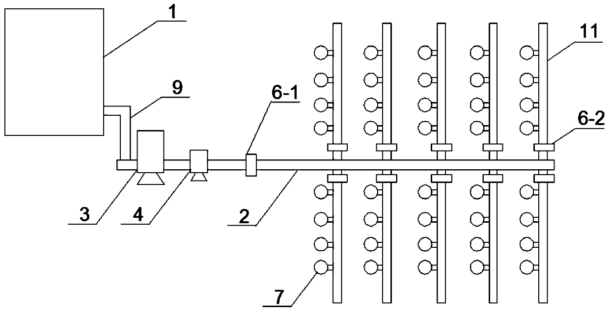
[0022] Embodiment 1, refer to figure 1 , figure 1 It is a schematic diagram of the overall structure of the sweet potato intelligent drip irrigation system of the present invention.
[0023] An intelligent drip irrigation cultivation system for sweet potatoes, comprising a water tank 1, the water tank 1 is connected to a main water pipeline 2 through a water inlet pipe 9, and a filtering device 3, a drip irrigation pump 4, and a first solenoid valve 6-1 are connected in series on the main water pipeline 2 ; The main water pipe 2 is provided with at least one branch pipe 11, and the branch pipe 11 is provided with a second electromagnetic valve 6-2 and a flowmeter at one end near the main water pipe 2, and the branch pipe 11 is provided with at least one A drip irrigation head 7, the branch pipe 11 is provided with a humidity sensor; the drip irrigation pump 4, the first solenoid valve 6-1, the second solenoid valve 6-2, the flow meter and the humidity sensor are all connected...
Embodiment 2
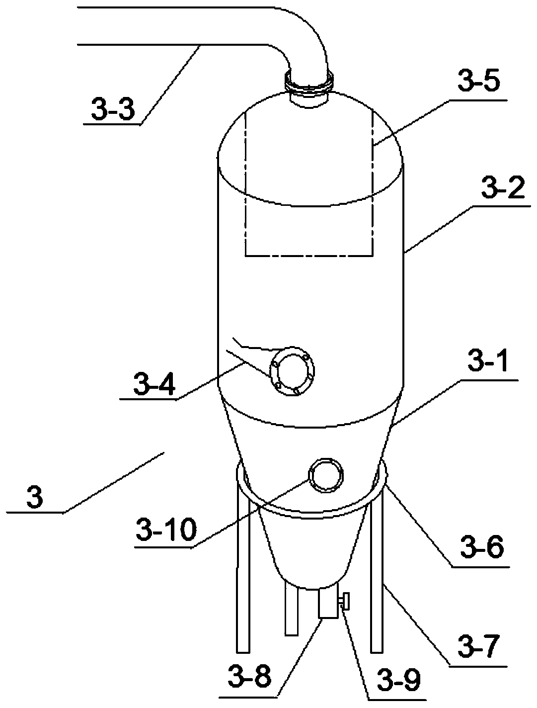
[0028] Embodiment 2, refer to figure 2 , figure 2 It is a structural schematic diagram of the filter device of the present invention.
[0029] The filter device 3 includes an upper cylinder 3-2 and a tapered lower cylinder 3-1 located at the bottom of the upper cylinder 3-2, and the upper cylinder 3-2 is provided with a water inlet pipe 3-2 along a tangential direction. 4. The top of the upper cylinder 3-2 is provided with a water outlet pipe 3-3, and the inside of the upper cylinder 3-2 is provided with a first filter net 3-5, and the first filter net 3-5 covers the Water pipe 3-3; the bottom of the tapered lower cylinder 3-1 is provided with a sewage outlet 3-8, and the sewage outlet 3-8 is provided with a first switch valve 3-9; the water inlet pipe 3-4 and The water outlet pipe 3-3 is connected in series on the main water pipe 2.
[0030] The working principle of the filter device 3 developed by the present invention is to use the principle of centrifugal separation t...
Embodiment 3
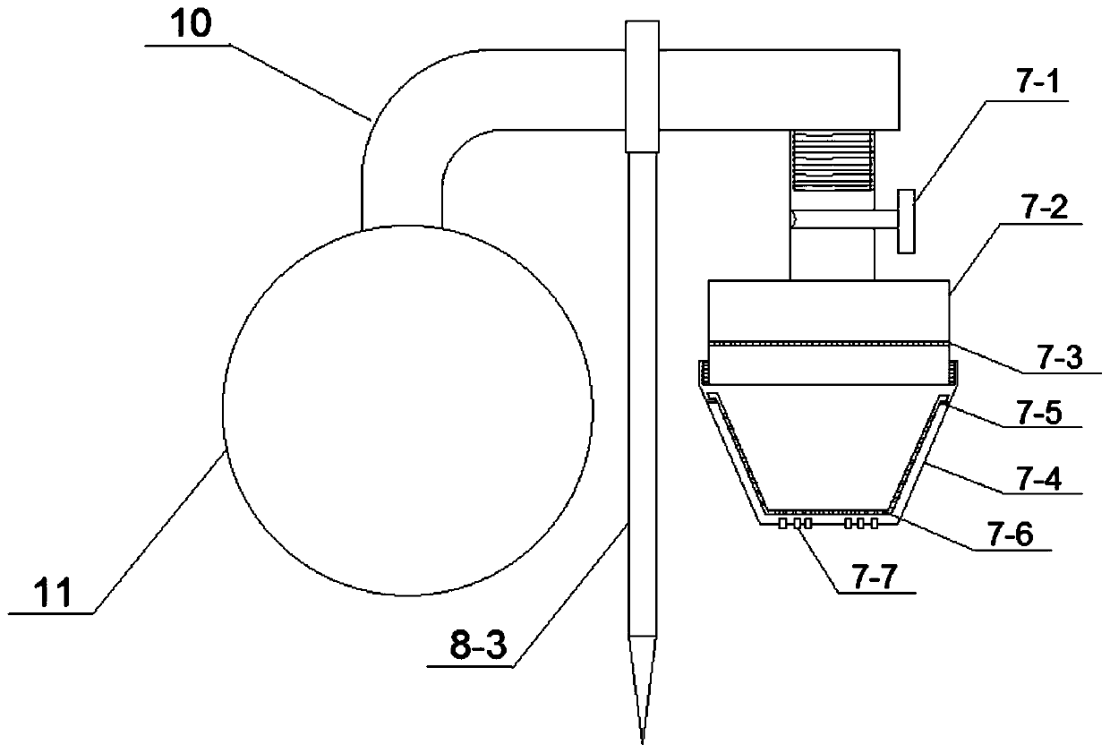
[0033] Embodiment 3, refer to image 3 , image 3 It is a structural schematic diagram of the drip irrigation head of the present invention.
[0034] The drip irrigation head 7 includes an upper drip irrigation cylinder 7-2 and a tapered lower drip irrigation cylinder 7-4 threadedly connected with the upper drip irrigation cylinder 7-2, and a second filter screen 7-3 is provided inside the upper drip irrigation cylinder 7-2 , the inner wall of the tapered lower drip irrigation tube 7-4 is provided with an annular limiting plate 7-5, and the annular limiting plate 7-5 is provided with a shape and size matching the inner wall of the tapered lower drip irrigation tube 7-4. A conical filter 7-6, the end of the conical drip irrigation tube 7-4 has a drip hole 7-7; the drip irrigation head 7 is threadedly connected to one end of the connecting pipe 10, and the other end of the connecting pipe 10 is connected to the Branch pipe 11 is connected.
[0035] The annular limiting plate ...
PUM
 Abstract
Description
Claims
Application Information
 - R&D Engineer
- R&D Manager
- IP Professional
- Industry Leading Data Capabilities
- Powerful AI technology
- Patent DNA Extraction
Browse by: Latest US Patents, China's latest patents, Technical Efficacy Thesaurus, Application Domain, Technology Topic, Popular Technical Reports.
© 2024 PatSnap. All rights reserved.Legal|Privacy policy|Modern Slavery Act Transparency Statement|Sitemap|About US| Contact US: help@patsnap.com


