
Separable full-profile subsurface buoy observation system and using method thereof

An observation system and separate technology, applied in buoys, measuring devices, surveying and navigation, etc., can solve the problems of limited equipment for flow velocity observation, difficulty in grasping the deployment distance, and shortage, so as to reduce the risk of equipment damage and comprehensive use The effect of low cost and meeting observation needs

Active Publication Date: 2020-06-30
OCEAN UNIV OF CHINA
View PDF10 Cites 11 Cited by
  • Summary
  • Abstract
  • Description
  • Claims
  • Application Information

AI Technical Summary

Problems solved by technology

However, at present, there is a serious shortage of on-site observation data on the effects of internal solitary waves on the deep-sea seabed surface. Therefore, an in-situ monitoring system is needed, which can simultaneously observe the dynamic changes of internal solitary waves and seabed boundary layer indicators. In order to further understand the impact of internal solitary waves on Provide necessary data support for research on scientific issues such as seabed interaction and wave-soil interaction in the hydrate test mining area
[0004] At present, submersible buoys are commonly used to observe internal waves. The common marine submersible buoy technology is relatively mature and reliable. It is generally composed of buoys (floating balls), observation equipment, cables, underwater acoustic releasers, counterweights, etc., and can obtain large-scale cross-sections. Temperature, salinity, and current velocity data, but difficult to observe near the seafloor, especially in the seafloor boundary layer
For the observation of the seabed boundary layer, the seabed foundation is mostly used. The ordinary seabed foundation can observe the temperature, pressure, displacement and other indicators of the seabed boundary layer. For example, the disclosed Chinese patent CN110254672A has realized the modular installation of the seabed foundation, and the disclosed patent CN110262258A The self-righting of the seabed foundation has been realized. In addition, Chinese patents CN206427251U and CN104816805A have all improved the observation of the seabed foundation, but none of them can observe the temperature profile of the overlying water body, and the profile range of the flow velocity observation is also limited by ADCP. Equipment, generally only a few hundred meters in range, seriously affects the application water depth
[0005] Although a separate seabed-based observation platform is stable and can be observed on the surface of the seabed, the observation range of the flow velocity of the large section of seawater above it is limited by the equipment, especially the temperature section cannot be observed; the submersible buoy can achieve large section observation, but many parameters close to the surface cannot be observed. If the submersible buoy chain is directly mounted on the seabed foundation, the seabed foundation will be shaken by the traction and pull of the submersible cable. The three-axis acceleration carried on the seabed foundation High-precision equipment such as sensors and high-precision pressure gauges can record false signals
However, if the two are deployed at the same place, it is not only difficult to grasp the deployment distance in ordinary operations, but also there is a potential risk of the submersible tag counterweight hitting the seabed foundation or the seabed foundation hook tripping the submersible tag chain.

Method used


Image

  • Separable full-profile subsurface buoy observation system and using method thereof
  • Separable full-profile subsurface buoy observation system and using method thereof
  • Separable full-profile subsurface buoy observation system and using method thereof

Examples


Embodiment Construction

[0052] In order to understand the above-mentioned purpose, features and advantages of the present invention more clearly, the present invention will be further described in detail below in conjunction with the accompanying drawings and specific embodiments. It should be noted that, in the case of no conflict, the embodiments of the present application and the features in the embodiments can be combined with each other.

[0053] In the following description, many specific details are set forth in order to fully understand the present invention. However, the present invention can also be implemented in other ways than described here. Therefore, the protection scope of the present invention is not limited by the specific implementation disclosed below. Example limitations.

[0054] Combine below Figure 1 to Figure 21 The anti-dumping columnar sediment sampler according to the embodiment of the present invention will be described in detail.

[0055] Such as figure 1 As shown, ...


PUM

PropertyMeasurementUnit
Lengthaaaaaaaaaa
Lengthaaaaaaaaaa

Abstract

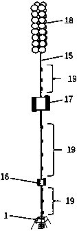
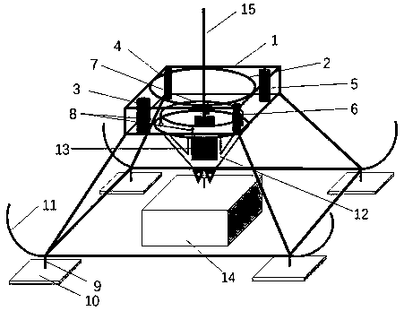
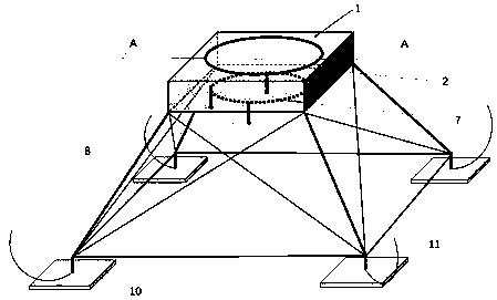
The invention provides a separable full-profile subsurface buoy observation system and a using method thereof. The separable full-profile subsurface buoy observation system comprises a subsurface buoyanchor chain system and a separable seabed base. A releasing device of the subsurface buoy anchor chain system comprises a clamping disc for fixing a seabed acoustic releaser and a cubic balance weight at the lower part, and is fixed in a seabed base through a corrosion bolt, and the clamping disc and the cubic balance weight are separated and are not in contact with each other. During recovery,the balance weight is unhooked, the clamping disc floats upwards, and the seabed base is dragged to the sea surface. According to the technical scheme of the invention, the seabed base and the subsurface buoy chain are combined in one set of observation system, are combined into one before laying, and are separated after laying completion, so that the advantages of the seabed base and the subsurface buoy observation system are combined; the operation can be completed through one-time laying; meanwhile, the requirements for seawater vertical large-section observation and observation of physicaland chemical indexes of a seabed surface boundary layer are met, a problem of equipment damage caused by potential sequential laying at the same station is solved, and traction shaking of the subsurface buoy chain to the seabed base in the extreme sea condition is avoided.

Description

technical field [0001] The present invention relates to the technical field of seabed exploration and the technical field of marine engineering geology, in particular to a detachable full-section submerged buoy observation system and its use method. Background technique [0002] The natural gas hydrate reserves on the northern slope of the South China Sea are huge. Under natural conditions or artificial mining conditions, hydrates will decompose, migrate upward along favorable paths such as faults or drill holes, and form secondary hydrates on the sea surface. Hydrates are sensitive to changes in pressure and temperature conditions. At the same time, the northern part of the South China Sea is a sea area where internal waves frequently develop, and the intensity of internal solitary waves in it ranks first in the world. During its propagation, it can affect the change of seabed surface pressure and bring the high-temperature seawater to the deep. Therefore, whether the int...

Claims


Application Information

Patent Timeline
IPC IPC(8): B63B22/00B63B22/04G01C13/00
CPCB63B22/00B63B22/04B63B2022/006G01C13/00
Inventor 贾永刚季春生胡乃利彭子奇陈天
Owner OCEAN UNIV OF CHINA
Learn More