A kind of spindle automatic assembly equipment and spindle assembly method using the same
An automatic assembly and spindle technology, applied in assembly machines, metal processing equipment, metal processing, etc., can solve problems such as reduced matching accuracy, and achieve the effects of avoiding thermal expansion, reducing interference, and solving the reduced matching accuracy.
- Summary
- Abstract
- Description
- Claims
- Application Information
AI Technical Summary
Problems solved by technology
Method used
Image
Examples
Embodiment 1
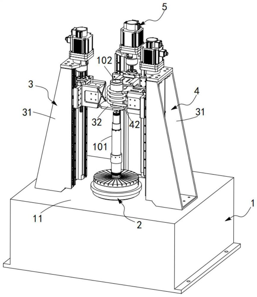
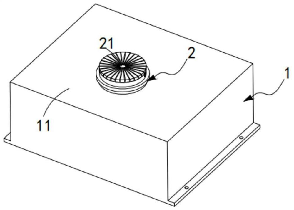
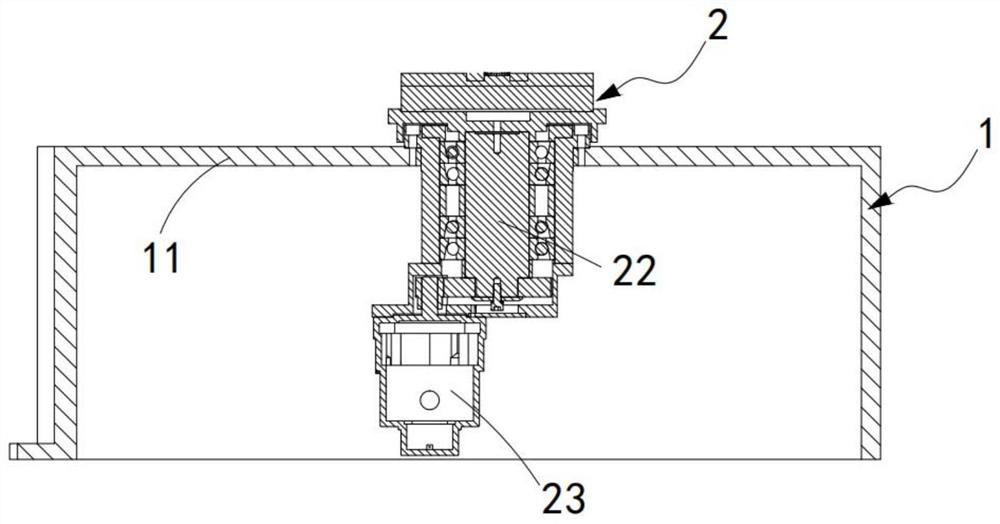
[0056] Such as Figures 1 to 11 As shown, a kind of spindle automatic assembly equipment includes a machine base 1 and an electro-permanent magnetic chuck 2. The electro-permanent magnetic chuck 2 is horizontally installed on the installation table 11 at the top of the machine base 1. The electro-permanent magnetic chuck 2 A mounting slot 21 for clamping and fixing the vertically arranged main shaft 101 is provided at the position of the axis, and also includes:
[0057] A lifting mechanism 3, the lifting mechanism 3 is installed on the installation table 11, and it is loaded with an annular workpiece 102 coaxially arranged with the main shaft 101 and slides vertically to fit the main shaft 101;
[0058] a heating mechanism 4, the heating mechanism 4 is installed on the installation table, it is adjacent to one side of the lifting mechanism 3, and it heats around the annular workpiece 102; and
[0059] An induction detection mechanism 5, the induction detection mechanism 5 is...
Embodiment 2
[0084] Figure 12 It is a structural schematic diagram of Embodiment 2 of an automatic spindle assembly equipment of the present invention; Figure 12 As shown, the components that are the same as or corresponding to those in the first embodiment are marked with the corresponding reference numerals in the first embodiment. For the sake of simplicity, only the differences from the first embodiment will be described below. This embodiment two and figure 1 The difference of the shown embodiment one is:
[0085] Such as Figure 12 As shown, a fixed installation opening 3163 is opened on the side installation surface 3162 perpendicular to the installation surface 3161 on the slider 316, and a fixed installation opening 3163 is opened on the installation back surface 3164 parallel to the installation surface 3161 on the slider 316. There are mounting notches 3165.
[0086] It should be noted that the sliding part 316 is used to install the bearing plate 32, the heating coil 42, ...
Embodiment 3
[0088] Embodiment 3 of the present invention is described with reference to Embodiment 1 to Embodiment 2, an assembly method using the spindle automatic assembly equipment described in any one of Embodiment 1 to Embodiment 2.
[0089] Such as Figure 13 shown, including the following steps:
[0090] Step 1, the main shaft is installed, the end of the main shaft 101 and the annular workpiece 102 are fitted and installed vertically upwards, so that the lower end of the main shaft 101 is vertically inserted into the installation groove 21 of the electro-permanent magnetic chuck 2, and the distance on the induction detection mechanism 5 After the sensor 53 detects that the verticality of the main shaft 101 is qualified, the main shaft 101 is adsorbed and fixed by the electro-permanent magnetic chuck 2;
[0091] Step 2: Install the ring-shaped workpiece. After the main shaft 101 is mounted and fixed, place the ring-shaped workpiece 102 on the loading plate 32 of the lifting mechan...
PUM
 Abstract
Description
Claims
Application Information
 - R&D
- Intellectual Property
- Life Sciences
- Materials
- Tech Scout
- Unparalleled Data Quality
- Higher Quality Content
- 60% Fewer Hallucinations
Browse by: Latest US Patents, China's latest patents, Technical Efficacy Thesaurus, Application Domain, Technology Topic, Popular Technical Reports.
© 2025 PatSnap. All rights reserved.Legal|Privacy policy|Modern Slavery Act Transparency Statement|Sitemap|About US| Contact US: help@patsnap.com


